4
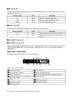
NIC status LED
The NIC status LED indicates the LAN status for the Ethernet connector 1 and Ethernet connector 2 on the
rear panel of the server.
NIC status LED
Color
Description
On
Green
The server is connected to a LAN.
Off
None
The server is disconnected from a LAN.
Blinking
Green
The LAN is connected and active.
5
System error LED
The system error LED helps you to determine if there are any system errors.
System error LED
Color
Description
On
Green
The booting process stops because of a POST error.
Off
None
The server is off or the server is on and working
correctly.
6
Front USB 2.0 connector 1
7
Front USB 2.0 connector 2
Used to attach a USB-compatible device, such as a USB keyboard, mouse, scanner, or printer. If you have
more than eight USB devices, you can purchase a USB hub, which you can use to connect additional
USB devices.
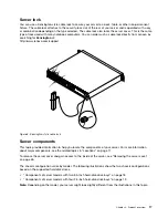
Rear view of the server
The following illustration shows the rear view of the server.
Figure 5. Rear view of the server
1
Power cord connector
2
Serial connector
3
Ethernet
connector
1
(RJ-45)
4
Ethernet
connector
2
(RJ-45)
5
USB 3.0 connectors (4)
6
Ethernet connector 0 for system management (RJ-45)
7
PCI Express card slot for the card installed on
the riser card assembly
8
Security-lock slot
9
ID LED
10
USB
2.0
connectors
(2)
11
DisplayPort connector
12
VGA DB-15 connector
13
Power cord retainer
14
ThinkServer RS140 User Guide and Hardware Maintenance Manual
Summary of Contents for ThinkServer RS140
Page 16: ...4 ThinkServer RS140 User Guide and Hardware Maintenance Manual ...
Page 18: ...6 ThinkServer RS140 User Guide and Hardware Maintenance Manual ...
Page 48: ...36 ThinkServer RS140 User Guide and Hardware Maintenance Manual ...
Page 122: ...110 ThinkServer RS140 User Guide and Hardware Maintenance Manual ...
Page 128: ...116 ThinkServer RS140 User Guide and Hardware Maintenance Manual ...
Page 132: ...120 ThinkServer RS140 User Guide and Hardware Maintenance Manual ...
Page 145: ......
Page 146: ......

