background image

• Use any documentation that comes with the new optical drive and follow those instructions in addition to

the instructions in this topic.

To remove the slim optical drive, do the following:

1. Remove all media from the drives and turn off all attached devices and the server. Then, disconnect all

power cords from electrical outlets and disconnect all cables that are connected to the server.

2. If the server is installed in a rack cabinet, remove the server from the rack cabinet and place it on a flat,

clean, and static-protective surface.

3. Remove the server cover. See “Removing the server cover” on page 55.

4. Locate the slim optical drive. See “Server components” on page 17.

5. Disconnect the cables from the rear of the slim optical drive.

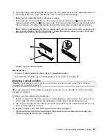
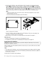
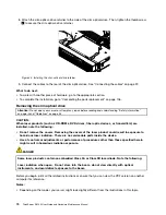
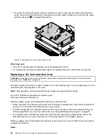
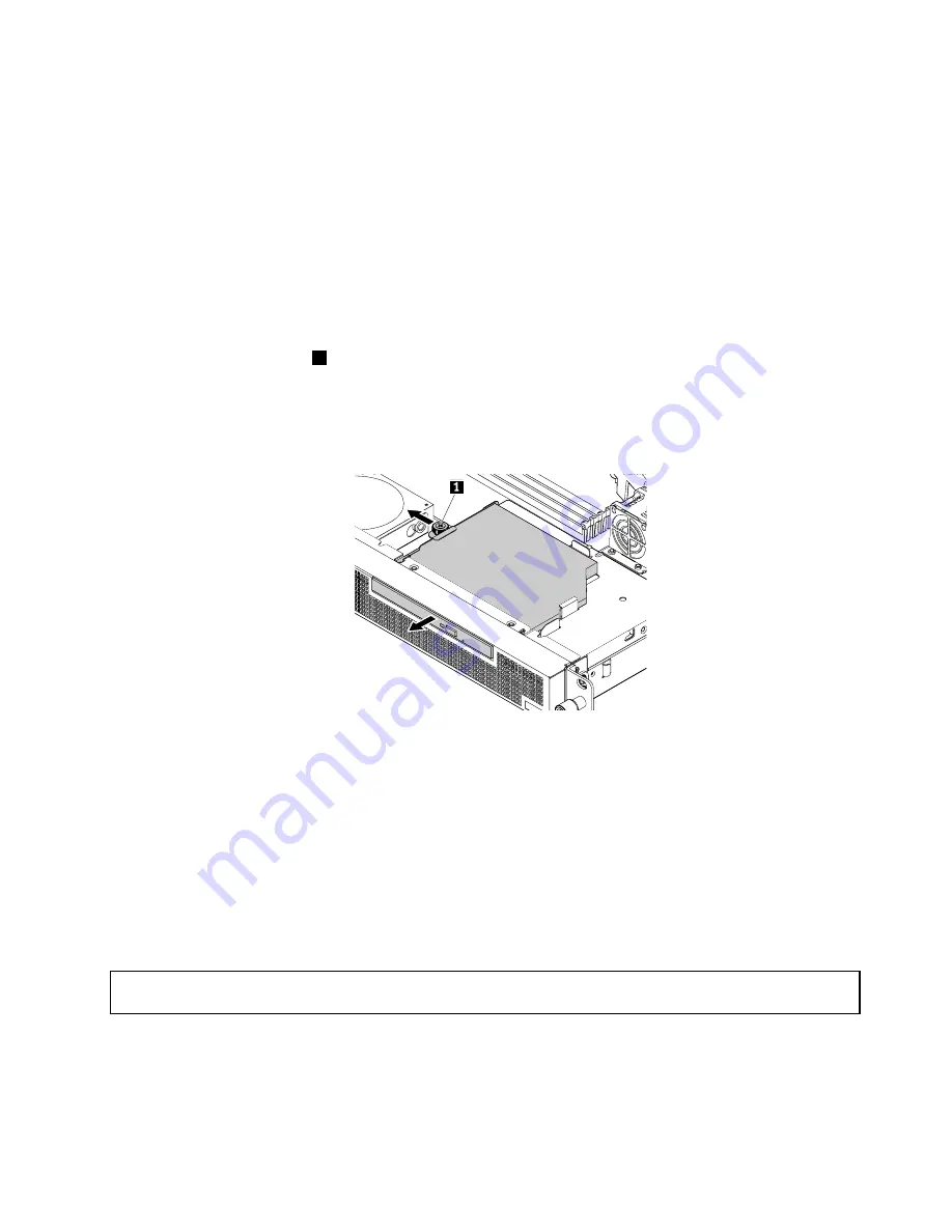
6. Loosen the thumbscrew

1

that secures the slim-optical-drive retainer and then remove the retainer from

the chassis. Slide the slim optical drive out of the front of the server.

Note:

The thumbscrew is an integrated part of the slim-optical-drive retainer. Do not try to remove the

thumbscrew from the retainer.

Figure 45. Removing the slim optical drive

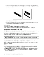
7. If you want to install a new slim optical drive, see “Installing the slim optical drive” on page 71.

8. If you are instructed to return the old optical drive, follow all packaging instructions and use any

packaging materials that are supplied to you for shipping.

What to do next:

• To work with another piece of hardware, go to the appropriate section.

• To complete the removal procedure, go to “Completing the parts replacement” on page 106.

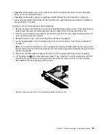
Replacing the riser card assembly

Attention:

Do not open your server or attempt any repair before reading and understanding “Safety information”

on page iii and “Guidelines” on page 53.

Before you begin, print all the related instructions or ensure that you can view the PDF version on another
computer for reference.

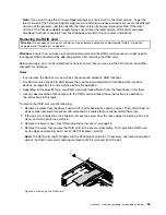
To replace the riser card assembly, do the following:

Chapter 6

.

Installing, removing, or replacing hardware

75

Summary of Contents for ThinkServer RS140

Page 1: ...ThinkServer RS140 User Guide and Hardware Maintenance Manual Machine Types 70F2 70F3 70F8 and 70F9 ...

Page 2: ... your product Safety information on page iii Appendix A Notices on page 121 First Edition May 2014 Copyright Lenovo 2014 LIMITED AND RESTRICTED RIGHTS NOTICE If data or software is delivered pursuant a General Services Administration GSA contract use reproduction or disclosure is subject to restrictions set forth in Contract No GS 35F 05925 ...

Page 3: ...Server EasyStartup program 45 Using the ThinkServer EasyStartup program on a Windows operating system 46 Configuring RAID 47 About RAID 47 RAID for your server 48 Configuring the system BIOS to enable onboard SATA RAID functionality 49 Configuring the advanced SATA or SAS hardware RAID 50 Configuring the Ethernet controllers 52 Updating the firmware 52 Using the Firmware Updater program 52 Chapter...

Page 4: ... Support Web site 117 Help and service 118 Before you call 118 Calling for service 118 Using other services 119 Purchasing additional services 119 Appendix A Notices 121 Trademarks 122 Important notes 122 Polyvinyl Chloride PVC cable and cord notice 122 Recycling information 123 Battery return program 123 Requirement for batteries containing perchlorate 124 Particulate contamination 124 Important ...

Page 5: ...teen käyttöä Avant d utiliser le produit veillez à bien lire et comprendre les instructions de sécurité multilingues figurant sur le DVD de documentation fourni avec le produit Πριν χρησιμοποιήσετε το προϊόν βεβαιωθείτε ότι έχετε διαβάσει και κατανοήσει τις οδηγίες ασφάλειας οι οποίες είναι διαθέσιμες σε διάφορες γλώσσες στο DVD τεκμηρίωσης που συνοδεύει το προϊόν Vor Verwendung des Produkts sollt...

Page 6: ... s produktom Preden začnete uporabljati izdelek je pomembno da preberete in razumete večjezična varnostna navodila na DVD ju z dokumentacijo ki ste ga prejeli skupaj z izdelkom Antes de utilizar el producto asegúrese de leer y comprender las instrucciones de seguridad multilingües del DVD de documentación que se proporciona con el producto Var noga med att läsa säkerhetsinstruktionerna på dokument...

Page 7: ...less instructed otherwise in the installation and configuration procedures Connect and disconnect cables as described in the following table when installing moving or opening covers on this product or attached devices To connect To disconnect 1 Turn everything OFF 2 First attach all cables to devices 3 Attach signal cables to connectors 4 Attach power cords to outlet 5 Turn devices ON 1 Turn every...

Page 8: ...ss 3B laser diode Note the following Laser radiation when open Do not stare into the beam do not view directly with optical instruments and avoid direct exposure to the beam Statement 4 18 kg 39 7 lb 32 kg 70 5 lb 55 kg 121 2 lb 32 kg 70 5 lb 55 kg 121 2 lb 100 kg 220 5 lb CAUTION Use safe practices when lifting Statement 5 CAUTION The power control button on the device and the power switch on the...

Page 9: ...oors will not support the weight of the device Statement 8 CAUTION Never remove the cover on a power supply or any part that has the following label attached Hazardous voltage current and energy levels are present inside any component that has this label attached There are no serviceable parts inside these components If you suspect a problem with one of these parts contact a service technician Sta...

Page 10: ...ded on the rails Statement 14 CAUTION Some accessory or option board outputs exceed Class 2 or limited power source limits You must install the appropriate interconnecting cabling in accordance with your local electrical code requirements Statement 15 CAUTION The power control button on the device may put the device in standby mode instead of turning off the device In addition the device might hav...

Page 11: ... 60 V direct current The branch circuit overcurrent protection must be rated in accordance with local electrical code requirements Use 1 3 mm2 or 16 American Wire Gauge AWG copper conductor only not exceeding 3 meters in length Torque the wiring terminal screws to 1 4 newton meters or 12 inch pounds Provide a readily available approved and rated disconnect device in the field wiring Statement 17 C...

Page 12: ...se only D40 or above air break switch to avoid unexpected power outage Products that are not assessed Typical products that are not assessed include but not limited to the following Server and IT rack components for example uninterruptible power supplies and current distribution systems Devices in IT rooms for example bulk storage units and network products Industrial low voltage switchgear x Thin...

Page 13: ...on DVD that comes with your server A printable generic version of the latest LLW also is available in more than 30 languages at http www lenovo com warranty llw_02 If you cannot obtain the LLW through the documentation DVD or Lenovo Web site contact your local Lenovo office or reseller to obtain a printed version of the LLW free of charge For warranty service consult the worldwide Lenovo Support t...

Page 14: ...n for your server and instructions on how to obtain all the documentation Printed document The following document is printed out and contained in your server package Read Me First This is a multilingual document you should read first This document guides you to read the complete warranty support and safety information on the documentation DVD that comes with your server before using the product Th...

Page 15: ...enovo warranty statement Customer Replaceable Units CRUs information and information about how to contact the Lenovo Customer Support Center Lenovo License Agreement This document includes the terms and conditions of the Lenovo License Agreement User Guide and Hardware Maintenance Manual This document provides detailed information to help you get familiar with your server and help you use configur...

Page 16: ...4 ThinkServer RS140 User Guide and Hardware Maintenance Manual ...

Page 17: ...he rail kit 4 Connect the Ethernet cables and the power cord to the server See Rear view of the server on page 14 to locate the connectors 5 Turn on the server to verify operation See Turning on the server on page 35 6 Review the Unified Extensible Firmware Interface UEFI Basic Input Output System BIOS settings and customize as needed See Using the Setup Utility program on page 37 7 Configure RAID...

Page 18: ...6 ThinkServer RS140 User Guide and Hardware Maintenance Manual ...

Page 19: ... your server might look slightly different from the following illustration ID Figure 1 Server package 1 Server 2 Material box including printed documentation a documentation DVD and software media 3 Power cord 4 Rail kit Features This topic provides general information about the server features for various models Depending on your specific model some features might vary or unavailable For informat...

Page 20: ...s that your server uses to read and store data The internal drives supported by your server vary by model Hard disk drive Up to two 3 5 inch Serial Advanced Technology Attachment SATA or Serial Attached SCSI SAS hard disk drives SCSI is the acronym for Small Computer System Interface Up to four 2 5 inch SATA or SAS hard disk drives or SATA solid state drives Note The term 2 5 inch hard disk drives...

Page 21: ...need it and the ease with which you can diagnose and correct problems Your server has the following RAS features Security features Administrator password and user password to help you protect unauthorized access to the server see Using passwords on page 41 ThinkServer Trusted Platform Module TPM which is a security chip to help enhance server security Note The TPM is only available in some models ...

Page 22: ...ications for your server Dimensions Width without rack handles 430 mm 16 9 inches Depth 411 mm 16 2 inches Height 43 5 mm 1 71 inches Weight The product weight varies depending on different system configurations Range of product weight with package 11 63 kg 25 64 lb to 13 16 kg 29 01 lb Environment Air temperature Operating 10 C to 35 C 50 F to 95 F Storage 40 C to 70 C 40 F to 158 F in original s...

Page 23: ...e 52 BIOS update utility The BIOS firmware keeps updating after the shipment of the server Lenovo maintains pages on the Support Web site and provides the BIOS update utility with instructions for download to help you update the BIOS firmware if needed For more information see Updating or recovering the BIOS on page 43 and Updating the firmware on page 52 RAID configuration utilities Your server s...

Page 24: ...4 Rack handle left 1 Front panel For detailed information about the controls connectors and status LEDs on the front panel see Front panel on page 13 2 Slim optical drive Some server models come with a slim SATA optical drive 3 Rack handle right 4 Rack handle left If your server is installed in a rack cabinet you can use the rack handles to help you slide the server out of the rack cabinet You als...

Page 25: ...ystem See Chapter 4 Turning on and turning off the server on page 35 The power status LED helps you to determine the current power status Power status LED Color Description On Green The server is on Off None The server is off 2 ID button with ID LED When you press the ID button on the front panel the ID LEDs on both the front and rear of the server are lit to help you locate the server among other...

Page 26: ...ctor 1 7 Front USB 2 0 connector 2 Used to attach a USB compatible device such as a USB keyboard mouse scanner or printer If you have more than eight USB devices you can purchase a USB hub which you can use to connect additional USB devices Rear view of the server The following illustration shows the rear view of the server Figure 5 Rear view of the server 1 Power cord connector 2 Serial connector...

Page 27: ...ualization Technology Figure 6 Ethernet status LEDs Table 1 Ethernet status LED 1 Color Status Description Amber On The connection speed is 1000 Mbps Green On The connection speed is 100 Mbps None Off The connection speed is 10 Mbps Table 2 Ethernet status LED 2 Color Status Description Amber On The server is connected to a LAN Amber Off The server is disconnected from a LAN Amber Blinking The LAN...

Page 28: ...e ID LEDs on both the front and rear of the server are lit to help you locate the server among other servers ID LED Color Description On Blue The server is identified Off None The ID LED is not in use or the server is not identified 11 DisplayPort connector Used to attach a high performance monitor a direct drive monitor or other devices that use a DisplayPort connector 12 VGA DB 15 connector Used...

Page 29: ...r components This topic provides information to help you locate the components of your server For more information about major components see the related topics in Locations on page 11 To remove the server cover and gain access to the inside of the server see Removing the server cover on page 55 The chassis configuration varies by model The following illustrations show the two chassis configuratio...

Page 30: ...server models with two 3 5 inch hard disk drive bays 1 Server cover 2 Riser card assembly 3 Ethernet card 4 Fan duct 5 System fan 1 6 Power supply assembly 7 System fan 3 8 Heat sink 9 Rack handle right 10 Microprocessor 11 Slim optical drive bracket 12 Slim optical drive 18 ThinkServer RS140 User Guide and Hardware Maintenance Manual ...

Page 31: ...ystem board Components of server models with four 2 5 inch hard disk drive bays 1 6 4 3 2 5 7 19 9 13 14 16 11 12 15 17 20 8 10 18 Figure 10 Components of server models with four 2 5 inch hard disk drive bays 1 Server cover 2 Riser card assembly 3 Ethernet card 4 Fan duct Chapter 3 Product overview 19 ...

Page 32: ...terms of the applicable warranty service type for your country or region Non CRUs must be replaced only by trained service technicians The following table lists the major FRUs in your server and the CRU identification information For a complete listing of FRU information such as FRU part numbers and supported server models go to http www lenovo com serviceparts lookup Notes Before servicing a Leno...

Page 33: ...cables that are not required for your server Your server supports the following RAID cards ThinkServer RAID 500 Adapter also known as ThinkServer 9240 8i RAID 0 1 Adapter ThinkServer RAID 700 Adapter also known as ThinkServer 9260 8i SAS RAID Adapter ThinkServer RAID 500 Adapter also known as ThinkServer 9240 8i RAID 0 1 Adapter The following illustration shows the connectors on the ThinkServer RA...

Page 34: ...ith SATA hard disk drives you can connect the SATA hard disk drives to a RAID card or the SATA connectors on the system board This topic provides instructions on the following cable connections Connecting the 2 5 inch hard disk drives and slim optical drive with a RAID card on page 22 Connecting the 2 5 inch hard disk drives and slim optical drive without a RAID card on page 25 Connecting the 3 5 ...

Page 35: ...re 13 Connecting the mini SAS connector to the RAID card 2 Connect one end of the SAS hard disk drive LED cable to the hard disk drive activity LED connector on the RAID card if supported 3 Install the RAID card to the riser card assembly See Installing the RAID card on page 62 4 Connect the other end of the SAS hard disk drive LED cable to the hard disk drive LED connector on the system board See...

Page 36: ... inch SAS combo cable to the hard disk drives 2 and 3 respectively d 6 Connect the power connector 2 of the mini SAS to 2 5 inch SAS combo cable to the other available 4 pin power connector on the system board For more information see System board components on page 32 Figure 14 Connecting the 2 5 inch hard disk drives 6 If you have a slim optical drive install the slim optical drive bracket and t...

Page 37: ...ector at the rear of the slim optical drive Note Ensure that the SATA cable and the power cable for the slim optical drive are routed under the power supply cable and the mini SAS to 2 5 inch SAS combo power cable Figure 15 Connecting the slim optical drive 8 Route the cables using the cable ties in the chassis See Reinstalling the server cover and reconnecting cables on page 106 Connecting the 2 ...

Page 38: ...k drives 2 and 3 respectively d 6 Connect the power connector 2 of the combo SAS cable to the other available 4 pin power connector on the system board For more information see System board components on page 32 Figure 16 Connecting the 2 5 inch hard disk drives 2 Connect the SATA connectors 0 to 3 of the combo SAS cable to the corresponding SATA connectors 0 to 3 respectively on the system board ...

Page 39: ...l drive power connector of a combo SAS cable to the power connector at the rear of the slim optical drive Note Ensure that the SATA cable and the power cable for the slim optical drive are routed under the power supply cable and the combo SAS power cable Figure 18 Connecting the slim optical drive 5 Route the cables using the cable ties in the chassis See Reinstalling the server cover and reconnec...

Page 40: ...e system board See System board components on page 32 5 Do the following to connect the hard disk drives a 1 Connect the SATA combo connector 0 of the mini SAS to 3 5 inch SAS combo cable to the hard disk drive 0 b 2 Connect the power connector of the mini SAS to 3 5 inch SAS combo cable to the 4 pin power connector which is near the memory modules on the system board c 3 Connect the SATA combo co...

Page 41: ...cal drive c 3 Connect the slim optical drive power connector of the mini SAS to 3 5 inch SAS combo cable to the power connector at the rear of the slim optical drive Figure 21 Connecting the slim optical drive Note Ensure that the SATA cable and the power cable for the slim optical drive are routed under the power supply cable and the mini SAS to SAS combo power cable 8 Route the cables using the ...

Page 42: ...rive 1 e 5 Connect the SATA connector of this combo SAS cable to the SATA 1 connector on the system board f 6 Connect the power connector of this combo SAS cable to the other available 4 pin power connector on the system board For more information see System board components on page 32 Figure 22 Connecting the 3 5 inch hard disk drives to the system board 2 If you have a slim optical drive install...

Page 43: ...combo SAS cable to the power connector at the rear of the slim optical drive For more information see System board components on page 32 Note Ensure that the SATA cable and the power cable for the slim optical drive are routed under the power supply cable and the combo SAS power cable Figure 23 Connecting the slim optical drive 4 Route the cables using the cable ties in the chassis See Reinstallin...

Page 44: ...13 SATA connector 0 14 SATA connector 4 15 SATA connector 1 16 SATA connector 2 17 System fan 2 connector 18 Front panel connector 19 Hard disk drive LED connector 20 Internal USB 2 0 connector 21 Clear CMOS Complementary Metal Oxide Semiconductor Recovery jumper 22 Manageability Engine ME disable jumper 23 Trusted Cryptography Module TCM connector 24 Riser card assembly slot 25 System fan 1 conne...

Page 45: ...to your hard disk drives 11 14 pin power connector Used to connect the power connector of the power supply to provide main power to your server 12 13 15 16 SATA connectors 0 3 Used to connect SATA signal cables for the hard disk drives 14 SATA connector 4 Used to connect the signal cable of the slim optical drive if your server has a slim optical drive installed 18 Front panel connector Used to co...

Page 46: ...ssembly slot Used to install the riser card assembly 26 Coin cell battery Your server has a special type of memory that maintains the date time and configuration information for built in features The coin cell battery keeps the information active when you turn off the server 34 ThinkServer RS140 User Guide and Hardware Maintenance Manual ...

Page 47: ...the server from the operating system if your operating system supports this feature After an orderly shutdown of the operating system the server will turn off automatically For instructions on how to shut down your specific operating system refer to the related documentation or help system for the operating system Press the power button on the front of the chassis to start an orderly shutdown of t...

Page 48: ...36 ThinkServer RS140 User Guide and Hardware Maintenance Manual ...

Page 49: ...assword you need to type the correct password to enter the Setup Utility program For password information see Using passwords on page 41 Viewing information in the Setup Utility program The Setup Utility program menu lists various items about the system configuration Select a desired item to view information or change settings When working with the Setup Utility program you must use the keyboard T...

Page 50: ...e various devices settings on the Devices menu in the Setup Utility program On each submenu press Enter to view the information or show selectable options and select a desired option by using the up and down arrow keys Some items are displayed on the menu only if the server supports the corresponding features Notes Enabled means that the function is configured Disabled means that the function is n...

Page 51: ...ine ICE Enable the system to enter the lower acoustic level or better thermal level Automatic Power On Enable or disable the Automatic Power On function Security menu You can set passwords and configure the TPM function on the Security menu in the Setup Utility program For each menu item press Enter to show selectable options and select a desired option by using the up and down arrow keys or type ...

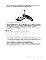
Page 52: ... Boot Sequence This sequence is used when a communication device wakes up the system Error Boot Sequence This sequence is used when an error occurs The Startup menu contains the following items CSM If you select Enabled you can install a non UEFI operating system If you select Disabled you can install a UEFI operating system Boot Mode Choose the boot policy Boot Priority Set the boot priority of o...

Page 53: ...r server However using a password improves computing security If you decide to set a password read the following topics Setup Utility program password types The following types of passwords are available in the Setup Utility program Administrator password Setting an administrator password deters unauthorized users from changing configuration settings If you are responsible for maintaining the conf...

Page 54: ...assword The previous password will be cleared Note For security reasons it is recommended that you always set a password for your server 5 Press F10 to save settings and exit the Setup Utility program If you have forgotten the password you can use the Clear CMOS jumper on the system board to erase the password See System board components on page 32 Then set a new password for the server Configurin...

Page 55: ...Exit Load Optimal Defaults For more information about the Exit menu in the Setup Utility program see Exit menu on page 40 Updating or recovering the BIOS This topic provides instructions on how to update the BIOS and how to recover from a POST and BIOS update failure System programs are the basic layer of software built into your server System programs include the POST the UEFI BIOS and the Setup ...

Page 56: ...s of configuring RAID and installing supported Windows and Linux operating systems VMware hypervisors and device drivers on your server The program works with your operating system installation disc to automate the process of installing the operating system and associated device drivers This program is provided with your server on a self starting bootable ThinkServer EasyStartup DVD The user guide...

Page 57: ...Startup program are German English Spanish French Italian Dutch Turkish Japanese and Russian 3 After selecting the language and keyboard layout click OK Then you will see one or more messages about configuring storage devices Click Next until you are presented with the Lenovo License Agreement Read the Lenovo License Agreement carefully In order to continue you must agree those terms by clicking A...

Page 58: ...r server configuration when you need them Note The most up to date device drivers for various server models are always available for download on the Lenovo Support Web site at http www lenovo com drivers About This menu provides the version information and legal notices Using the ThinkServer EasyStartup program on a Windows operating system You can run the ThinkServer EasyStartup DVD on a Windows ...

Page 59: ... distributed across the drives in one of several ways called RAID levels When a group of independent physical hard disk drives are set up to use RAID technology they are in a RAID array This array distributes data across multiple hard disk drives but the array appears to the host server as one single storage unit Creating and using RAID arrays provides high performance such as the expedited I O pe...

Page 60: ...D 10 a combination of RAID 0 and RAID 1 RAID 10 consists of striped data across mirrored spans A RAID 10 drive group is a spanned drive group that creates a striped set from a series of mirrored drives RAID 10 allows a maximum of eight spans You must use an even number of drives in each RAID virtual drive in the span The RAID 1 virtual drives must have the same stripe size RAID 10 provides high da...

Page 61: ...ted operating systems and device drivers Before configuring RAID for your server observe the following precautions 1 Use hard disk drives that have the same capacity within a single RAID array 2 Use hard disk drives that are of the same type SATA or SAS within a single RAID array 3 Depending on the operating system the primary RAID might be limited to 2 TB total drive capacity Configuring the syst...

Page 62: ... ROM configuration utility during system startup 2 Use the up and down arrow keys to select Reset Disks to Non RAID and press Enter 3 Use the arrow keys and the space key to mark individual physical hard disk drives to be reset and then press Enter to complete the selection 4 When prompted press Y to confirm the reset action 5 After resetting the hard disk drives to non RAID you can See Deleting R...

Page 63: ... drives attached to the controller and the RAID level selected Supports hot spare drives Creates a RAID response file that can be used to configure RAID controllers on similarly configured Lenovo servers See Using the ThinkServer EasyStartup program on page 44 and view the user guide from the main interface of the program Some RAID management software also is provided on the ThinkServer EasyStartu...

Page 64: ...lable for download at http www lenovo com drivers Updating the firmware The firmware in the server is periodically updated and is available for download on the Lenovo Web site Go to http www lenovo com drivers and follow the instructions on the Web page to check for the latest level of firmware such as the BIOS updates and device drivers When you replace a device in the server you might have to ei...

Page 65: ...your server go to http www lenovo com drivers and follow the instructions on the Web page See Updating the firmware on page 52 for more information Before you install optional hardware devices ensure that the server is working correctly If the server is not working correctly see Chapter 7 Troubleshooting and diagnostics on page 111 to do basic troubleshooting If the problem cannot be solved see Ch...

Page 66: ...ch the static protective package containing the new part to an unpainted metal part of the server for at least two seconds This reduces static electricity from the package and your body Remove the new part from the static protective package and directly install it in the server without placing it on any other surface If it is hard for you to do this in your specific situation place the static prot...

Page 67: ...while the server is running Operating the server without the air ducts or air baffles might cause the microprocessors to overheat For servers that support up to two microprocessors ensure that the second microprocessor socket always contains a microprocessor or is protected by a microprocessor socket cover Removing the server cover Attention Do not open your server or attempt any repair before rea...

Page 68: ... on how to install remove or replace hardware for your server You can expand the capabilities of your server by adding new hardware devices such as memory modules PCI Express cards or other server options and maintain your server by replacing the failing hardware devices If you are handling a server option refer to the appropriate installation and or removal instructions in this topic along with t...

Page 69: ... 1 that secure the rack handle and then remove the rack handle from the chassis Figure 26 Removing the rack handles 4 To reinstall each rack handle ensure that the screw holes in the rack handle are aligned with the corresponding holes in the chassis Then install the two screws to secure the rack handle 5 Go to Completing the parts replacement on page 106 Removing and reinstalling the fan duct Att...

Page 70: ...cable to the fan duct Lift the fan duct out of the server 1 Figure 27 Removing the fan duct 5 To reinstall the fan duct note the orientation of the fan duct and then place it above the heat sink Then lower the fan duct into the chassis until it is secured into place Figure 28 Installing the fan duct 6 Route the 4 pin power cable under the tabs on the fan duct and then connect the 4 pin power cable...

Page 71: ...technology The minimum system memory is 2 GB only one 2 GB memory module installed in the DIMM2 slot The maximum system memory is 32 GB one 8 GB memory module installed in each of the four memory slots For more information about the memory modules in your specific server model use the Setup Utility program See Viewing information in the Setup Utility program on page 37 For a list of supported Thin...

Page 72: ...ule installation rules on page 59 Use any documentation that comes with the memory module and follow those instructions in addition to the instructions in this topic To install a memory module do the following 1 Remove all media from the drives and turn off all attached devices and the server Then disconnect all power cords from electrical outlets and disconnect all cables that are connected to th...

Page 73: ...rdware go to the appropriate section To complete the installation go to Completing the parts replacement on page 106 Removing a memory module Attention Do not open your server or attempt any repair before reading and understanding Safety information on page iii and Guidelines on page 53 Before you begin print all the related instructions or ensure that you can view the PDF version on another compu...

Page 74: ...server to provide advanced hardware RAID functions For more information see RAID card on page 21 and Configuring RAID on page 47 Installing the RAID card Attention Do not open your server or attempt any repair before reading and understanding Safety information on page iii and Guidelines on page 53 Attention Ensure that you back up your data before installing the RAID card because you might need t...

Page 75: ...sembly in the server See Server components on page 17 5 Remove the screw that secures the PCI Express card slot bracket and then remove the bracket from the chassis Store it in case you later remove the PCI Express card and need the bracket to cover the place Figure 33 Removing a PCI Express card slot bracket 6 Touch the static protective package that contains the new RAID card to any unpainted su...

Page 76: ...at to do next To work with another piece of hardware go to the appropriate section To complete the installation go to Completing the parts replacement on page 106 Then configure RAID for your server See Configuring RAID on page 47 After you install a Lenovo RAID card do the following 1 Check the firmware version of the new RAID card firmware by pressing Ctrl H when starting the Setup Utility progr...

Page 77: ... card is sensitive to ESD Ensure that you read and understand Handling static sensitive devices on page 54 first and carefully perform the operation Depending on the specific type your RAID card might look different from the illustrations in this topic Use any documentation that comes with the RAID card and follow those instructions in addition to the instructions in this topic To remove the RAID ...

Page 78: ... page iii and Guidelines on page 53 Attention Back up your data before you begin if you want to reconfigure RAID and reinstall the operating system after installing the TR 500 Key Before you begin print all the related instructions or ensure that you can view the PDF version on another computer for reference Note Use any documentation that comes with the TR 500 Key and follow those instructions in...

Page 79: ...comes with your server for information about how to configure the hardware RAID Removing the TR 500 Key Attention Do not open your server or attempt any repair before reading and understanding Safety information on page iii and Guidelines on page 53 Attention Back up your data before you begin if you need to reconfigure RAID and reinstall the operating system after removing the TR 500 Key Before y...

Page 80: ...e TR 500 Key you might need to reconfigure RAID for your server Refer to the MegaRAID SAS Software User Guide on the documentation DVD that comes with your server for information about how to configure the hardware RAID Installing or removing the ThinkServer RAID 700 Battery This topic provides instructions on how to install or remove the ThinkServer RAID 700 Battery hereinafter referred to as the...

Page 81: ...c To install the TR 700 Battery do the following 1 Remove all media from the drives and turn off all attached devices and the server Then disconnect all power cords from electrical outlets and disconnect all cables that are connected to the server 2 If the server is installed in a rack cabinet remove the server from the rack cabinet and place it on a flat clean and static protective surface See th...

Page 82: ...ThinkServer RAID 700 Adapter with the TR 700 Battery on the riser card assembly See Installing or removing the RAID card on page 62 8 Reinstall the riser card assembly See Replacing the riser card assembly on page 75 What to do next To work with another piece of hardware go to the appropriate section To complete the installation go to Completing the parts replacement on page 106 Removing the TR 70...

Page 83: ...the TR 700 Battery on page 69 7 Reinstall the ThinkServer RAID 700 Adapter onto the riser card assembly See Installing or removing the RAID card on page 62 8 Reinstall the riser card assembly See Replacing the riser card assembly on page 75 What to do next To work with another piece of hardware go to the appropriate section To complete the removal procedure go to Completing the parts replacement o...

Page 84: ...ion to the instructions in this topic To install the slim optical drive do the following 1 Remove all media from the drives and turn off all attached devices and the server Then disconnect all power cords from electrical outlets and disconnect all cables that are connected to the server 2 If the server is installed in a rack cabinet remove the server from the rack cabinet and place it on a flat cl...

Page 85: ...ew from the retainer Figure 42 Removing the slim optical drive retainer 6 Touch the static protective package that contains the slim optical drive to any unpainted surface on the outside of the server Then take the slim optical drive out of the package 7 Slide the slim optical drive into the chassis from the front of the server Figure 43 Installing the slim optical drive Chapter 6 Installing remov...

Page 86: ...ptic devices or transmitters are installed note the following Do not remove the covers Removing the covers of the laser product could result in exposure to hazardous laser radiation There are no serviceable parts inside the device Use of controls or adjustments or performance of procedures other than those specified herein might result in hazardous radiation exposure DANGER Some laser products con...

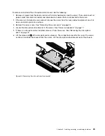
Page 87: ...ptical drive out of the front of the server Note The thumbscrew is an integrated part of the slim optical drive retainer Do not try to remove the thumbscrew from the retainer Figure 45 Removing the slim optical drive 7 If you want to install a new slim optical drive see Installing the slim optical drive on page 71 8 If you are instructed to return the old optical drive follow all packaging instruc...

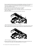
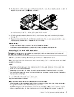
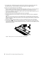
Page 88: ... on the riser card assembly remove the card See Removing the RAID card on page 65 6 Remove the two screws that secure the riser card assembly to the chassis Figure 46 Removing the screws that secure the riser card assembly 7 Open the retaining clip that secures the riser card assembly in the riser card assembly slot on the system board Grasp the riser card assembly by its edges and carefully lift ...

Page 89: ...ard assembly See Installing the RAID card on page 62 14 If you are instructed to return the old riser card assembly follow all packaging instructions and use any packaging materials that are supplied to you for shipping What to do next To work with another piece of hardware go to the appropriate section To complete the replacement go to Completing the parts replacement on page 106 Replacing the Et...

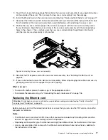
Page 90: ...e See Replacing the riser card assembly on page 75 6 Disconnect the Ethernet card ID LED cable from the Ethernet card 7 Remove the two screws that secure the Ethernet card to the riser card assembly Then grasp the Ethernet card by its edges and carefully pull it out of the PCI Express card slot Figure 49 Removing the Ethernet card 8 Touch the static protective package that contains the new Etherne...

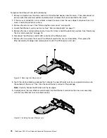
Page 91: ...opriate section To complete the replacement go to Completing the parts replacement on page 106 Replacing the Ethernet card ID LED cable To replace the Ethernet card ID LED cable do the following 1 Remove all media from the drives and turn off all attached devices and the server Then disconnect all power cords from electrical outlets and disconnect all cables that are connected to the server 2 If t...

Page 92: ...th the cable ties in the chassis 12 Flex the two sides of the plastic retaining clip and then insert the ID LED into the plastic retaining clip to secure the ID LED 13 Connect the Ethernet card ID LED cable to the Ethernet card If you have removed the riser card assembly reinstall it into the chassis See Replacing the riser card assembly on page 75 What to do next To work with another piece of har...

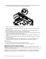
Page 93: ...eference Note Use any documentation that comes with the new power supply assembly and follow those instructions in addition to the instructions in this topic To replace the power supply assembly do the following 1 Remove all media from the drives and turn off all attached devices and the server Then disconnect all power cords from electrical outlets and disconnect all cables that are connected to ...

Page 94: ...pply assembly Figure 54 Installing the screws to secure the power supply assembly 9 Connect the power cables to the system board See System board components on page 32 10 Reinstall the server cover See Reinstalling the server cover and reconnecting cables on page 106 11 Connect the power cord to the power cord connector on the new power supply assembly 12 If you are instructed to return the old po...

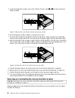
Page 95: ...ective surface 3 Remove the server cover See Removing the server cover on page 55 4 Locate the slim optical drive bracket in the server See Server components on page 17 5 If there is a slim optical drive installed remove it from the server See Removing the slim optical drive on page 74 6 Lift the release pin 1 of the slim optical drive bracket Then slide the bracket to the rear of the server as sh...

Page 96: ...cedure is the same Note This procedure must be performed only by trained service personnel of Lenovo For a list of ThinkServer hard disk drive options go to http www lenovo com thinkserver Before you begin review the following hard disk drive installation rules Follow the order of the hard disk drive bays when installing a hard disk drive See Server components on page 17 to locate the hard disk dr...

Page 97: ... flat clean and static protective surface 3 Remove the server cover See Removing the server cover on page 55 4 Locate the appropriate 2 5 inch hard disk drive that you want to replace See Server components on page 17 Note If you want to remove the 2 5 inch hard disk drives that are installed under the slim optical drive bracket remove the slim optical drive bracket first See Removing and reinstall...

Page 98: ...the bracket Figure 58 Removing the 2 5 inch hard disk drive from the bracket 8 Position the new 2 5 inch hard disk drive into the bracket and then install the four screws to secure the new 2 5 inch hard disk drive Figure 59 Installing the 2 5 inch hard disk drive to the bracket 86 ThinkServer RS140 User Guide and Hardware Maintenance Manual ...

Page 99: ...ained service personnel of Lenovo Before you begin print all the related instructions or ensure that you can view the PDF version on another computer for reference Notes Depending on the model your server might come with 3 5 inch hard disk drives 2 5 inch hard disk drives or 2 5 inch solid state drives Depending on the model your server might look slightly different from the illustrations in this ...

Page 100: ...the server cover on page 55 4 Locate the appropriate 3 5 inch hard disk drive that you want to replace See Server components on page 17 Note If you want to remove the 3 5 inch hard disk drive that is installed under the slim optical drive bracket remove the slim optical drive bracket first See Removing and reinstalling the slim optical drive bracket on page 82 5 Disconnect the SATA combo connector...

Page 101: ... bracket Figure 62 Removing the 3 5 inch hard disk drive from the bracket 8 Position the new 3 5 inch hard disk drive into the bracket and then install the four screws to secure the new 3 5 inch hard disk drive Figure 63 Installing the 3 5 inch hard disk drive to the bracket Chapter 6 Installing removing or replacing hardware 89 ...

Page 102: ...performed only by trained service personnel of Lenovo Before you begin print all the related instructions or ensure that you can view the PDF version on another computer for reference Notes The front panel board is sensitive to ESD Ensure that you read and understand Handling static sensitive devices on page 54 first and carefully perform the operation Depending on the model your server might look...

Page 103: ... front panel board by its edges 9 Connect all the cables to the new front panel board 10 Carefully position the new front panel board so that the two screw holes in the front panel board are aligned with the corresponding holes in the chassis Then install the screws to secure the front panel board in place Figure 66 Installing the front panel board 11 Reinstall the hard disk drives in the server i...

Page 104: ...ook slightly different from the illustrations in this topic To replace a system fan do the following 1 Remove all media from the drives and turn off all attached devices and the server Then disconnect all power cords from electrical outlets and disconnect all cables that are connected to the server 2 If the server is installed in a rack cabinet remove the server from the rack cabinet and place it ...

Page 105: ...facing the rear of the server Then press the new system fan straight down until it is seated into place Figure 68 Installing the system fan 9 Connect the system fan cable to the system board See System board components on page 32 Note If you are replacing the system fan 1 that is near the rear of the server reinstall the riser card assembly to the system board See Replacing the riser card assembly...

Page 106: ...for reference Note Depending on the model your server might look slightly different from the illustrations in this topic To replace the heat sink do the following 1 Remove all media from the drives and turn off all attached devices and the server Then disconnect all power cords from electrical outlets and disconnect all cables that are connected to the server 2 If the server is installed in a rack...

Page 107: ...nk off the system board 8 Lay aside the old heat sink Touch the static protective package that contains the new heat sink to any unpainted surface on the outside of the server Then remove the new heat sink from the package Notes If you are replacing a heat sink you must use a cleaning pad that might come with the new heat sink to wipe the thermal grease from the top of the microprocessor before in...

Page 108: ...e 70 Installing the screws to secure the heat sink 11 Reinstall the fan duct See Removing and reinstalling the fan duct on page 57 12 If you are instructed to return the old heat sink follow all packaging instructions and use any packaging materials that are supplied to you for shipping What to do next To work with another piece of hardware go to the appropriate section To complete the replacement...

Page 109: ...roprocessor socket and socket cover might look slightly different from the illustrations in this topic To replace the microprocessor do the following 1 Remove all media from the drives and turn off all attached devices and the server Then disconnect all power cords from electrical outlets and disconnect all cables that are connected to the server 2 If the server is installed in a rack cabinet remo...

Page 110: ...the microprocessor and carefully lift it straight up and out of the microprocessor socket Place the old microprocessor on a static protective surface Notes Do not touch the gold contacts on the bottom of the microprocessor Do not drop anything onto the microprocessor socket while it is exposed The socket pins must be kept as clean as possible Figure 72 Removing the microprocessor 8 Touch the stati...

Page 111: ...n and secure the new microprocessor in the socket 12 Reinstall the heat sink See Replacing the heat sink on page 94 13 Reinstall the fan duct See Removing and reinstalling the fan duct on page 57 14 If you are instructed to return the old microprocessor follow all packaging instructions and use any packaging materials that are supplied to you for shipping What to do next To work with another piece...

Page 112: ...rate Material special handling may apply See www dtsc ca gov hazardouswaste perchlorate Before you begin print all the related instructions or ensure that you can view the PDF version on another computer for reference To replace the coin cell battery do the following Note After you replace the coin cell battery you must reset passwords reset system date and time and reconfigure the server 1 Remove...

Page 113: ...empt any repair before reading and understanding Safety information on page iii and Guidelines on page 53 Note This procedure must be performed only by trained service personnel of Lenovo CAUTION Hazardous moving parts Keep fingers and other body parts away CAUTION The heat sinks and microprocessors might be very hot Turn off the server and wait three to five minutes to let the server cool before ...

Page 114: ... and cable routing in the server 5 Remove the fan duct See Removing and reinstalling the fan duct on page 57 6 Remove the heat sink See Replacing the heat sink on page 94 7 Remove the riser card assembly See Replacing the riser card assembly on page 75 8 Remove all memory modules See Removing a memory module on page 61 9 Record the cable routing and cable connections Then disconnect all the cables...

Page 115: ...andle the system board by its edges Leave the black Mylar under the old system board in the chassis 13 Place the old system board on a clean flat and static protective surface Touch the static protective package that contains the new system board to any unpainted surface on the outside of the server Then take the new system board out of the package 14 Install the new system board into the chassis ...

Page 116: ...e the system board 16 Reinstall the two hexagonal screws 1 to secure the rear of the system board to the chassis Figure 79 Reinstalling the two hexagonal screws to secure the rear of the system board 17 Remove the protective cover that protects the pins on the microprocessor socket on the new system board 104 ThinkServer RS140 User Guide and Hardware Maintenance Manual ...

Page 117: ... in the chassis See Removing and reinstalling the fan duct on page 57 22 Install the memory modules on the new system board See Installing a memory module on page 60 23 Install the riser card assembly on the new system board See Replacing the riser card assembly on page 75 24 Install the coin cell battery on the new system board See Replacing the coin cell battery on page 99 25 Install any other p...

Page 118: ...onnect all the external cables and for some devices update the firmware and run the Setup Utility program to do further setup Reinstalling the server cover and reconnecting cables Attention Do not open your server or attempt any repair before reading and understanding Safety information on page iii and Guidelines on page 53 Attention For proper cooling and airflow reinstall the server cover before...

Page 119: ...e fan duct and the server cover The following illustration shows an example of the cable routing in the chassis with two 3 5 inch hard disk drives and a RAID card Figure 81 An example of cable routing server models with two 3 5 inch hard disk drives and a RAID card 3 If you have removed the fan duct reinstall it See Removing and reinstalling the fan duct on page 57 Chapter 6 Installing removing or...

Page 120: ...RU Information about this will come with the CRU or will come a few days after the CRU arrives Updating the server configuration When you turn on the server for the first time after you install remove or replace a device you might need to update the server configuration Some optional devices have device drivers that you must install For information about installing device drivers use the documenta...

Page 121: ... ThinkServer EasyStartup program see Using the ThinkServer EasyStartup program on page 44 To update your system firmware see Updating the firmware on page 52 Chapter 6 Installing removing or replacing hardware 109 ...

Page 122: ...110 ThinkServer RS140 User Guide and Hardware Maintenance Manual ...

Page 123: ...e the logo screen to view any diagnostic messages 6 Download and use a diagnostic program to diagnose problems See Using a diagnostic program on page 111 7 Refer to Basic troubleshooting tables on page 112 and follow the instructions for the type of problem you are experiencing If the basic troubleshooting information does not help you resolve a problem continue with the next step 8 Try using a pr...

Page 124: ...am and has a bootable DVD drive installed or a bootable external DVD drive attached 2 Ensure that you have set the optical drive with the ThinkServer EasyStartup DVD installed as the first startup device See Selecting a startup device on page 42 3 Verify if the optical drive or the disc has problems See Optical drive problems on page 112 The operating system installation program continuously loops...

Page 125: ...ained service technician only Replace the system board A disc is not working correctly 1 Ensure that the disc is in the optical drive with the shiny side facing down 2 Ensure that the disc surface is clean and not scratched 3 Check the disc or package for regional coding You might need to purchase a disc with coding for the region where you are using the product 4 Restart the disc player program 5...

Page 126: ...e actions solve the problem see Troubleshooting procedure on page 111 for the subsequent steps you should check after using the information in this topic If the problem still cannot be solved seek technical assistance See Chapter 8 Getting information help and service on page 117 Notes If you are instructed to remove install or replace any CRUs refer to the related procedure in Chapter 6 Installin...

Page 127: ...r 3 Replace the keyboard The mouse or pointing device does not work 1 Ensure that The mouse or pointing device cable is securely connected to the server If the USB mouse or pointing device is connected to a USB hub disconnect the mouse or pointing device from the hub and connect it directly to the server The mouse or pointing device is clean and no dust accumulates The device drivers are installed...

Page 128: ...116 ThinkServer RS140 User Guide and Hardware Maintenance Manual ...

Page 129: ... To access the Lenovo Support Web site go to http www lenovo com support For more information about your server documentation see Server documentation on page 2 If you suspect a software problem refer to the documentation including readme files and online help that comes with the operating system or software program ThinkServer Web site The ThinkServer Web site provides up to date information and ...

Page 130: ...e warranty period you can get help and information by telephone through the Customer Support Center The following services are available during the warranty period Problem determination Trained service personnel are available to assist you with determining a hardware problem and deciding what action is necessary to fix the problem Hardware repair If the problem is caused by hardware under warranty...

Page 131: ...rvice is delivered through the method of service such as depot carry in or on site service that is provided in the servicing country Service centers in certain countries might not be able to service all models of a particular machine type In some countries fees and restrictions might apply at the time of service To determine whether your computer is eligible for International Warranty Service and ...

Page 132: ...120 ThinkServer RS140 User Guide and Hardware Maintenance Manual ...

Page 133: ...e publication Lenovo may make improvements and or changes in the product s and or the program s described in this publication at any time without notice The products described in this document are not intended for use in implantation or other life support applications where malfunction may result in injury or death to persons The information contained in this document does not affect or change Len...

Page 134: ...ferring to hard disk drive capacity or communications volume MB stands for 1 000 000 bytes and GB stands for 1 000 000 000 bytes Total user accessible capacity can vary depending on operating environments Maximum internal hard disk drive capacities assume the replacement of any standard hard disk drives and population of all hard disk drive bays with the largest currently supported drives that are...

Page 135: ...ve 2006 66 EC concerning batteries and accumulators and waste batteries and accumulators The Directive determines the framework for the return and recycling of used batteries and accumulators as applicable throughout the European Union This label is applied to various batteries to indicate that the battery is not to be thrown away but rather reclaimed upon end of life per this Directive In accorda...

Page 136: ...rmines that the levels of particulates or gases in your environment have caused damage to the server Lenovo may condition provision of repair or replacement of servers or parts on implementation of appropriate remedial measures to mitigate such environmental contamination Implementation of such remedial measures is a customer responsibility Table 4 Limits for particulates and gases Contaminant Lim...

Page 137: ...cts of EEE on the environment and human health due to the presence of hazardous substances For additional WEEE information go to http www lenovo com recycling Restriction of Hazardous Substances Directive RoHS This topic provides statements about the Restriction of Hazardous Substances Directive RoHS Turkish RoHS The Lenovo product meets the requirements of the Republic of Turkey Directive on the ...

Page 138: ...mmended cables and connectors or by unauthorized changes or modifications to this equipment Unauthorized changes or modifications could void the user s authority to operate the equipment This device complies with Part 15 of the FCC Rules Operation is subject to the following two conditions 1 this device may not cause harmful interference and 2 this device must accept any interference received incl...

Page 139: ... EMVG früher Gesetz über die elektromagnetische Verträglichkeit von Geräten Dies ist die Umsetzung der EU Richtlinie 2004 108 EG früher 89 336 EWG in der Bundesrepublik Deutschland Zulassungsbescheinigung laut dem Deutschen Gesetz über die elektromagnetische Verträglichkeit von Betriebsmitteln EMVG vom 20 Juli 2007 früher Gesetz über die elektromagnetische Verträglichkeit von Geräten bzw der EMV E...

Page 140: ...m die Einhaltung des EMVG sicherzustellen sind die Geräte wie in den Handbüchern angegeben zu installieren und zu betreiben Eurasian compliance mark 128 ThinkServer RS140 User Guide and Hardware Maintenance Manual ...

Page 141: ...ving 61 documentation using 117 E EasyUpdate Firmware Updater program using 52 Ethernet card replacing 77 Ethernet connectivity features 9 Ethernet controllers configuring 52 Ethernet status LED 15 Ethernet card ID LED cable replacing 79 Exit menu Setup Utility program 40 exiting Setup Utility program 43 expansion slot features 8 export classification notice 126 F fan duct reinstalling 57 removing...

Page 142: ...nes 59 microprocessor features 8 replacing 96 N NIC status LED 14 O optical drive removing 74 option completing the replacement 106 P particulate contamination 124 parts replacement completing 106 password considerations 41 setting changing deleting 42 Setup Utility program 41 Power menu Setup Utility program 39 power status LED 13 power supply features 8 power supply assembly replacing 80 precaut...

Page 143: ...tup Utility program 40 static sensitive devices guidelines 54 static sensitive devices handling 54 system board 32 replacing 101 system board components locations 32 system date setting 41 system fan features 8 replacing 92 system identification ID LED 13 16 system reliability guidelines 55 system status LED 14 system time setting 41 T the BIOS flashing 43 updating 43 updating or recovering 43 Thi...

Page 144: ...pdate Firmware Updater program 52 passwords 41 Setup Utility program 37 ThinkServer EasyStartup program 44 V video subsystem features 9 viewing information Setup Utility program 37 W Web site compatible options 59 132 ThinkServer RS140 User Guide and Hardware Maintenance Manual ...

Page 145: ......

Page 146: ......

Reviews: