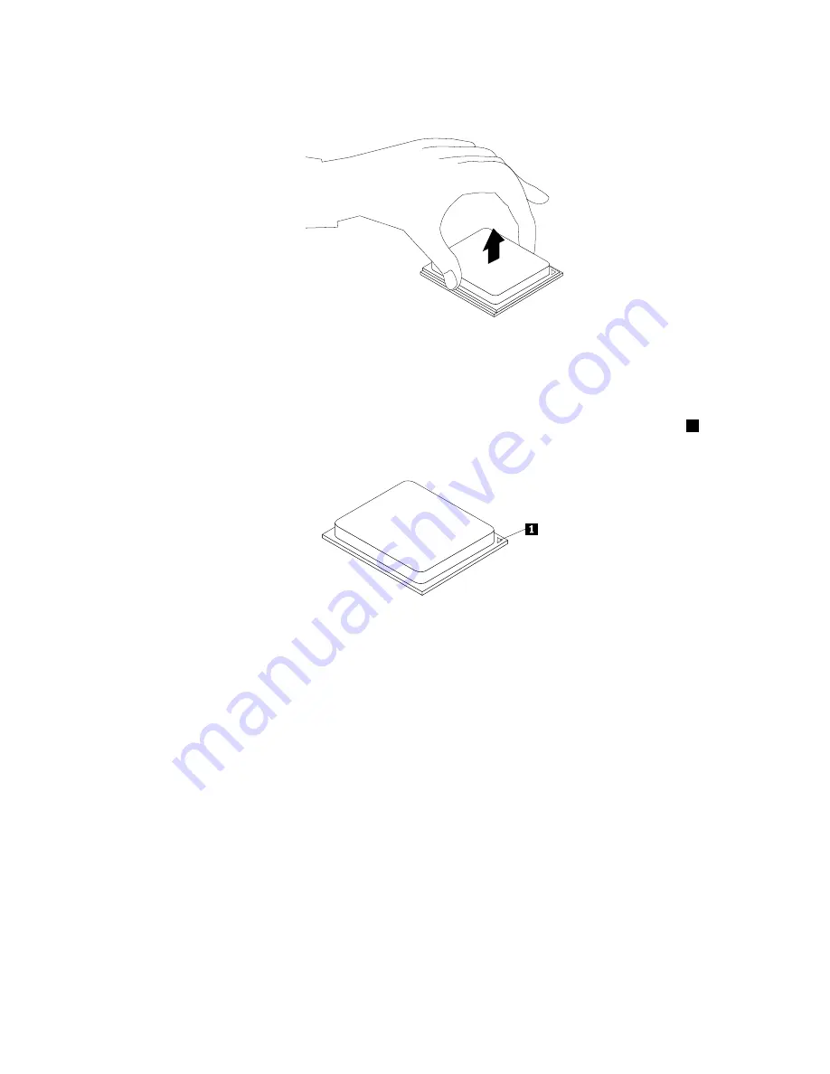
6. Lift the microprocessor straight up and out of the microprocessor socket.
Figure 51. Removing the microprocessor
Notes:
• Your microprocessor and socket might look different from the one illustrated.
• Note the orientation of the microprocessor in the socket. You can look for the small triangle
1
on one corner of the microprocessor. This is important when installing the new microprocessor
on the system board.
• Touch only the edges of the microprocessor. Do not touch the gold contacts on the bottom.
• Do not drop anything onto the microprocessor socket while it is exposed. The socket pins must be
kept as clean as possible.
7. Ensure that the small handle is in the raised position.
8. Remove the protective cover that protects the gold contacts of the new microprocessor.
9. Hold the new microprocessor by its sides and align the small triangle on one corner of the new
microprocessor with the corresponding small triangle on one corner of the microprocessor socket.
10. Lower the new microprocessor straight down into the microprocessor socket on the system board.
11. Lower the small handle to secure the new microprocessor in the socket.
12. Reinstall the heat sink and fan assembly with the fan duct. See “Replacing the heat sink and fan
assembly” on page 126.
13. Reconnect all cables that were disconnected from the system board.
What to do next:
• To work with another piece of hardware, go to the appropriate section.
• To complete the replacement, go to “Completing the parts replacement” on page 151.
134
ThinkCentre M79 Hardware Maintenance Manual
Summary of Contents for ThinkCentre M79
Page 1: ...ThinkCentre M79 Hardware Maintenance Manual Machine Types 10CT 10CU 10CV and 10CW ...
Page 6: ...iv ThinkCentre M79 Hardware Maintenance Manual ...
Page 8: ...vi ThinkCentre M79 Hardware Maintenance Manual ...
Page 16: ... 18 kg 37 lb 32 kg 70 5 lb 55 kg 121 2 lb 8 ThinkCentre M79 Hardware Maintenance Manual ...
Page 19: ...1 2 Chapter 1 Read this first Important safety information 11 ...
Page 20: ...1 2 12 ThinkCentre M79 Hardware Maintenance Manual ...
Page 21: ...Chapter 1 Read this first Important safety information 13 ...
Page 27: ...Chapter 1 Read this first Important safety information 19 ...
Page 31: ...Chapter 1 Read this first Important safety information 23 ...
Page 40: ...Figure 4 Component locations 32 ThinkCentre M79 Hardware Maintenance Manual ...
Page 68: ...Figure 8 Installing a padlock 60 ThinkCentre M79 Hardware Maintenance Manual ...
Page 80: ...72 ThinkCentre M79 Hardware Maintenance Manual ...
Page 98: ...90 ThinkCentre M79 Hardware Maintenance Manual ...
Page 112: ...104 ThinkCentre M79 Hardware Maintenance Manual ...
Page 168: ...160 ThinkCentre M79 Hardware Maintenance Manual ...
Page 172: ...164 ThinkCentre M79 Hardware Maintenance Manual ...
Page 175: ...Appendix D China Energy Label Copyright Lenovo 2014 167 ...
Page 176: ...168 ThinkCentre M79 Hardware Maintenance Manual ...
Page 178: ...170 ThinkCentre M79 Hardware Maintenance Manual ...
Page 184: ...176 ThinkCentre M79 Hardware Maintenance Manual ...
Page 185: ......
Page 186: ......


