


7. Connect one end of the signal cable to the rear of the new hard disk drive and the other end to an
available SATA connector on the system board. See “Locating parts on the system board” on page 34.
Then, locate an available four-wire power connector and connect it to the rear of the new hard disk drive.
Figure 24. Connecting a SATA hard disk drive
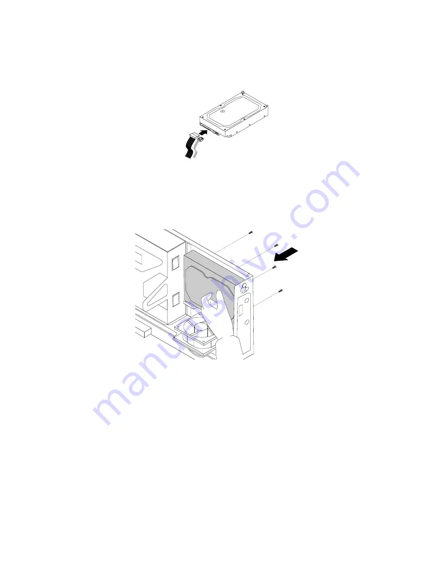
8. Position the new hard disk drive into the hard disk drive bay and align the screw holes in the new hard
disk drive with the corresponding holes in the drive bay. Then, install the four screws to secure the
new hard disk drive in place.
Figure 25. Installing the hard disk drive
What to do next:
• To work with another piece of hardware, go to the appropriate section.
• To complete the installation or replacement, go to “Completing the parts replacement” on page 151.
Replacing the solid-state drive
Attention:
Do not open your computer or attempt any repair before reading and understanding the Chapter
1 “Read this first: Important safety information” on page 1.
The solid-state drive is only available on some models. It might be installed in the hard disk drive bay or
on the bottom of the optical drive bay.
• To replace the solid-state drive in the hard disk drive bay, see “Replacing the solid-state drive in the hard
disk drive bay” on page 117.
• To replace the solid-state drive on the bottom of the optical drive bay, see “Replacing the solid-state drive
on the bottom of the optical drive bay” on page 118.
116
ThinkCentre M79 Hardware Maintenance Manual
Summary of Contents for ThinkCentre M79
Page 1: ...ThinkCentre M79 Hardware Maintenance Manual Machine Types 10CT 10CU 10CV and 10CW ...
Page 6: ...iv ThinkCentre M79 Hardware Maintenance Manual ...
Page 8: ...vi ThinkCentre M79 Hardware Maintenance Manual ...
Page 16: ... 18 kg 37 lb 32 kg 70 5 lb 55 kg 121 2 lb 8 ThinkCentre M79 Hardware Maintenance Manual ...
Page 19: ...1 2 Chapter 1 Read this first Important safety information 11 ...
Page 20: ...1 2 12 ThinkCentre M79 Hardware Maintenance Manual ...
Page 21: ...Chapter 1 Read this first Important safety information 13 ...
Page 27: ...Chapter 1 Read this first Important safety information 19 ...
Page 31: ...Chapter 1 Read this first Important safety information 23 ...
Page 40: ...Figure 4 Component locations 32 ThinkCentre M79 Hardware Maintenance Manual ...
Page 68: ...Figure 8 Installing a padlock 60 ThinkCentre M79 Hardware Maintenance Manual ...
Page 80: ...72 ThinkCentre M79 Hardware Maintenance Manual ...
Page 98: ...90 ThinkCentre M79 Hardware Maintenance Manual ...
Page 112: ...104 ThinkCentre M79 Hardware Maintenance Manual ...
Page 168: ...160 ThinkCentre M79 Hardware Maintenance Manual ...
Page 172: ...164 ThinkCentre M79 Hardware Maintenance Manual ...
Page 175: ...Appendix D China Energy Label Copyright Lenovo 2014 167 ...
Page 176: ...168 ThinkCentre M79 Hardware Maintenance Manual ...
Page 178: ...170 ThinkCentre M79 Hardware Maintenance Manual ...
Page 184: ...176 ThinkCentre M79 Hardware Maintenance Manual ...
Page 185: ......
Page 186: ......


