


6. MULTI-SCREEN DISPLAY FEATURE (MULTI)
57
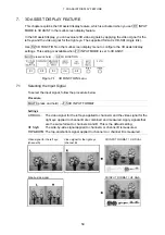
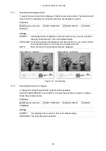
6.8.2
Selecting the Channels To Display
When F•5 3D INPUT FORMAT is set to L/R DUAL, follow the procedure below to select the
channels to display on the histograms.
Procedure
MULTI (press and hold)
→
F•4 DISPLAY FORM
→
F•2 HISTGRM SETUP
→
F•2 L/R
SELECT
Settings
LEFT:
Channel A (the video signal for the left eye) is displayed.
RIGHT:
Channel B (the video signal for the right eye) is displayed.
L&R:
Channel A (the video signal for the left eye) and channel B (the video signal
for the right eye) are displayed on top of each other. This is the default
setting.
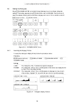
6.8.3
Turning Y, R, G, and B On and Off
When F•1 HISTGRM FORM is set to OVERLAY, follow the procedure below to turn Y, R, G,
and B on and off separately. You cannot turn all channels off.
Procedure
MULTI (press and hold)
→
F•4 DISPLAY FORM
→
F•2 HISTGRM SETUP
→
F•3
YRGB SELECT
→
F•1 Y
→
F•2 R
→
F•3 G
→
F•4 B
Settings
ON:
The Y, R, G, or B signal is displayed. This is the default setting.
OFF:
The Y, R, G, or B signal is not displayed.
6.9
User-Defined Layout Settings
You can display the measurement screen with a user-defined layout that you set in advance.
To create a layout file, contact your local LEADER agent.
Press F•5 USER LAYOUT on the Multi-Screen Display menu to set the display to a
user-defined layout. This setting appears when F•1 INPUT MODE is set to SINGLE or DUAL
and a USB memory device that contains layout files is connected to the LV 5380.