background image

6-40

Machine transportation after setup > Procedure for the main unit transportation (Truck transportation)

[CONFIDENTIAL]

28

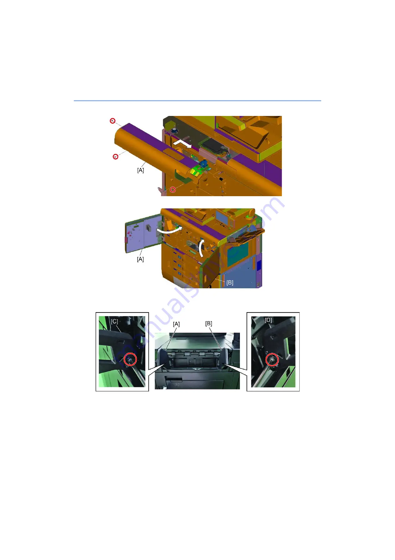
Reattach the left front upper cover to the original position. (Screw x3)

29

Close the front left upper cover [A] and the front right upper cover [B].

30

Attach the front width guide [C] to the front guide bracket [A]. (Screw x1)

31

Attach the rear width guide [D] to the front guide bracket [B]. (Screw x1)

Summary of Contents for AK-9110

Page 1: ...vember 2019 Version 3 0 CONFIDENTIAL AK 9110 AK 9120 AK 9130 AK 9140 Banner Guide 11 BF 9110 DE 9100 DF 9100 PF 9100 PF 9110 PH 7A PH 7C PH 7D Printing System 50 SL 9100 ST 9100 TASKalfa Pro 15000c Installation Guide ...

Page 2: ...aste officials for details in your area for proper disposal ATTENTION IL Y A UN RISQUE D EXPLOSION SI LA BATTERIE EST REMPLACEE PAR UN MODELE DE TYPE INCORRECT METTRE AU REBUT LES BATTERIES UTILISEES SELON LES INSTRUCTIONS DONNEES Il peut être illégal de jeter les batteries dans des eaux d égout municipales Vérifiez avec les fonctionnaires municipaux de votre région pour les détails concernant des...

Page 3: ...estination page 2 50 page 2 52 page 2 54 page 2 55 page 6 56 page 6 58 page 6 60 page 6 61 Added the note for procedure of changing yellow color page 2 42 page 6 1 page 6 12 page 6 14 page 6 52 Deleted the procedure of setting temperature page 2 2 Add other maintenance mode page 2 47 Add the setup wizard screen page 2 62 Add detail of the other maintenance mode 2 6 ...

Page 4: ...ur service personnel to ensure the safety of their customers their machines as well as themselves during maintenance activities Service personnel are advised to read this booklet carefully to familiarize themselves with the warnings and precautions described here before engaging in maintenance activities ...

Page 5: ...this symbol CAUTION Bodily injury or damage to property may result from insufficient attention to or incorrect com pliance with warning messages using this symbol Symbols The triangle symbol indicates a warning including danger and caution The specific point of attention is shown inside the symbol General warning Warning of risk of electric shock Warning of high temperature indicates a prohibited ...

Page 6: ...chine in a humid or dusty place This may cause fire or electric shock Do not install the machine near a radiator heater other heat source or near flammable material This may cause fire Allow sufficient space around the machine to allow the ventilation grills to keep the machine as cool as possible Insufficient ventilation may cause heat buildup and poor copying performance Always handle the machin...

Page 7: ... carefully Always check that the machine is correctly connected to an outlet with a ground connection Check that the power cable covering is free of damage Check that the power plug is dust free If it is dirty clean it to remove the risk of fire or electric shock Handle the charger sections with care They are charged to high potentials and may cause electric shock if handled improperly CAUTION Wea...

Page 8: ...solvents with care by following the instructions below Use only a small amount of solvent at a time being careful not to spill Wipe spills off completely Ventilate the room well while using grease or solvents Allow applied solvents to evaporate completely before refitting the covers or turning the power switch on Always wash hands afterwards Never dispose of ink or ink bottles in fire Ink may caus...

Page 9: ...This page is intentionally left blank ...

Page 10: ...2 9 1 Store the protective caps for shipping 2 35 2 4 Ink initial supply Set up flow 2 37 1 Initial ink supply to the print head 2 38 2 5 Adjustment 2 48 1 Image check flow 2 48 2 Head position adjustment 2 50 3 Print position adjustment Print position 2 58 2 6 Other maintenance mode 2 62 1 Setup in a high altitude Maintenance mode U732 2 62 2 Output maintenance report Maintenance mode U000 2 62 3...

Page 11: ...Fiery Print Server Printing System 50 and Printing System Interface Kit 50 3 38 3 3 Optional devices installation 3 39 1 Feed enhancement 3 39 2 Input enhancement Accessories 3 95 3 Output enhancement 3 99 3 1 Output 3 1 3 99 3 2 Output 3 2 Output 3 3 Output 3 4 3 127 4 Output enhancement Accessories 3 197 4 1 Output 4 1 Folding Unit for 4000 Sheet Finisher BF 9110 3 197 4 2 Output 4 2 Hole Punch ...

Page 12: ...3 CONFIDENTIAL 6 2 Procedure for the main unit transportation Truck transportation 6 14 1 Before transportation 6 14 2 Install after transportation 6 32 3 Adjustment 6 54 3 1 Image check flow 6 54 ...

Page 13: ...ironment such as a small enclosed room the operation may emit an unpleasant smell Proper ventilation of the room is important when considering setup location 1 Temperature 59 to 86 F 15 to 30 C Humidity should be 54 or less in 86 F 30 C 2 Humidity 15 to 80 RH Temperature should be 80 6 F 27 C or less in 80 RH 3 Product name Rated voltage Rated current Power requirements Main unit AC120V 60Hz 8 5A ...

Page 14: ... is 5 mm x 4 places 2 This size include the total clearance between each device which is 5 mm x 2 places NOTE The unevenness of the floor is 5 mm or less Fix a location for the main unit then install the optional unit 800 4460 6060 Front side Rear side PF 9100 AK 9110 Main unit DE 9100 DF 9100 470 1054 965 1200 751 2240 1000 500 800 1534 1961 ...

Page 15: ...l clearance between each device which is 5 mm x 4 places 2 This size include the total clearance between each device which is 5 mm x 2 places 800 2926 4526 Front side Rear side Main unit DE 9100 DF 9100 965 1200 751 2240 1000 500 800 1961 800 4609 6209 Front side Rear side PF 9100 AK 9110 Main unit DE 9100 ST 9100 470 1054 965 1200 900 2240 1000 500 800 2110 1534 ...

Page 16: ...tween each device which is 5 mm x 9 places 2 This size include the total clearance between each device which is 5 mm x 5 places 3 This size include the total clearance between each device which is 5 mm x 4 places 800 5840 7440 Front side Rear side PF 9100 AK 9110 Main unit DE 9100 ST 9100 AK 9120 DF 9100 470 1054 965 1200 900 470 751 2240 1000 500 800 3341 1534 800 8139 9739 Front side Rear side P...

Page 17: ...ase Remove the scanner carriage stopper and put it back in an opposite way Image conveying unit Remove the fixing screws and the plates Pull out the image conveying unit and remove the screws for the image conveying unit Place the image conveying unit on a table and remove the fixing plates for the unit Head Treatment unit Remove the fixing plates Remove the fixing parts for the cap unit Remove th...

Page 18: ...rint head Syringe of the Ink and the cleaning liquid the air vent and fill up for the circulation pipe and the filter Perform set up mode Replace the preserving liquid in the print head unit to the ink and the cleaning liquid by purging and filling up Remove nozzle clogging purge U744 Adjustment Head position adjustment Check head position adjustment U468 Head top timing adjustment U469 Head overl...

Page 19: ...Set altitude U732 Output maintenance report U000 Clearing the counts U927 Setting the delivery date U278 Store the setting value at setup U023 End of the main unit installation After completing adjustments of the main unit then setup the enhancement ...

Page 20: ... wipe unit 302TJ4154 and Tray 302TJ4155 Jig Tool Slope For taking main unit or enhancement down from palette 302TJ94E5 PARTS SLOPE SET UP SP Consumable Alfa wipe TX 1000 Series Clean ink around ink tube coupler Consumable Kim towel white or BEMCOT or Wypall 60X 70X At setting cleaning liquid tank in case of getting wet Consumable Designated deionized water Deionized water PR 9435A R 950 32 or the ...

Page 21: ...CONFIDENTIAL Ink manufacturing date display Notation contents 1st from left Production year 9 2019 2nd from left Production month January to September X October Y November Z December Collection box Boxed container Single color container ...

Page 22: ...cessory case 6 Outer case 7 Main unit 8 Main unit cover 9 Operation pad 10 Upper pad 11 Waste ink tank 12 Right exit tray 13 Holder case 14 Empty case 15 Cleaning liquid tank 16 Top case IMPORTANT Do not lift up and move the main unit by holding handles only The handles are just used for changing the direction or cross over a small gap ...

Page 23: ...the upper case A 2 Remove 12 hinges and take out the outer case B 3 Take out two empty cases B and the cleaning liquid tank C first and then take out the holder case A Take out the right exit tray D waste ink tank F and then take out the upper pads E 4 Remove 4 lower pads A and the accessory case 5 Remove the main unit cover B A B A A D E F A B C A B ...

Page 24: ...ch each 2 pads When working support the machine not to fall down and be careful not to pinch the hands or feet 8 Cut off the carton board shown in red frame D for placing the slope 9 Hang pins B on the backside of the slope onto bottom plate of the skid then set the slope A 10 Move through the main unit C from the skid using the slope A CAUTION Do not lift up and move the main unit by holding hand...

Page 25: ...type about 36kg 79lbs For storing fold Loosen the wing screw B and unfold the slope A For use unfold CAUTION The slope has to be held by 2 persons and pay attention not to pinch the finger or thorn This slope is used for the main unit and DE Service parts 302TJ94E5 PARTS SLOPE SET UP SP ...

Page 26: ...e lift plate stopper B and attach it to the storage location 3 Remove the tape from the spacer C 4 Re insert cassette 1 A and repeat same procedures step 1 to 3 for cassette 2 as well 2 Deck lift plate 1 Pull out cassette 3 A 2 Remove the lift plate stopper B and attach it to the storage location 3 Re insert cassette 3 A and repeat same procedures 1 to 2 for cassette 4 as well ...

Page 27: ... 1 Open the DP B hold up the triangle mark side of the optical lock cover A and slide it then remove it 2 Attach the cover A in the opposite direction and releases the scanner carriage Place triangle symbol to the front for releasing IMPORTANT C3100 comes up if failing to release the scanner carriage ...

Page 28: ...B 2 Pull out the image conveying unit C Screw x4 3 Remove the screw on the bottom of the image conveying unit A Screw x4 The screw has a tag B IMPORTANT In case of difficult to remove the screw remove the screw C by sliding it to the aperture while slightly lifting the front A or the rear B of the image conveying belt unit screw x4 C C C C A B View after removing image conveying belt unit Screw sl...

Page 29: ... on a table Take care not to damage the electrical components 5 Remove the right side bracket B from the image conveying unit A Screw x7 6 Remove the left side bracket B from the image conveying unit A Screw x8 IMPORTANT Pay attention when handling the print conveying belt unit the lift wire might come off if lifting up the lift plate from the bottom A B C C ...

Page 30: ...ve the transport brackets reverse winding error comes up as the lift wire gets loosen and the unit can not drive downward from the removal position after power on C2740 Conveying belt lower limit sensor error C2750 Conveying belt wire reverse winding error See page 5 10 for the corrective action of service call ...

Page 31: ...move the transportation spacers CONFIDENTIAL 5 Head Treatment unit Remove the fixing plates 1 Remove the upper left cover A Screw x11 2 Remove the screw of the cap front plate A Screw x1 3 Remove the screw of the cap rear plate A Screw x1 ...

Page 32: ...ard and pull it out slightly 5 Remove the screw from the lower side of the cap front plate A with the screwdriver then remove the plate Screw x1 The screw has a tag B 6 Remove the screw from the lower side of the cap rear plate A with the screwdriver then remove the plate Screw x1 The screw has a tag B A B A B ...

Page 33: ... Confirm if the center of the shaft B matches with center of position C 8 Remove the treatment front plate A Screw x2 9 Remove the treatment rear plate A Screw x2 IMPORTANT If forgetting to remove the cap plate C2100 will occur C2100 Treatment carriage HP sensor error See page 5 1 for the corrective action of service call A B C A A ...

Page 34: ...nit setup procedure Remove the transportation spacers CONFIDENTIAL IMPORTANT If forgetting to remove the treatment plate C2100 will occur After removing the fixing plate it will recover by turning on the power switch ...

Page 35: ...es 2 Open the front right upper cover A and the front left upper cover B 3 Remove the left front upper cover A in the direction of the arrow Screw x3 IMPORTANT Floor flatness 0 3 degree or less Inclination has to be less than 5 mm against the main unit length 1 000 mm Load capacity 350 kg m2 or more In order to keep the level and adjust it accurate it is recommended that place firm plates or panel...

Page 36: ...them as all casters slightly up from floor at the end Make sure to adjust the above because the main unit might move if the casters are not up slightly when clearing the jam by moving the enhancement devices and locate it back to the original position due to pushing the main unit by the enhancement devices 5 Reattach the left front upper cover to the original position Screw x3 ...

Page 37: ...2 21 The main unit setup procedure Installation CONFIDENTIAL 6 Close the front left upper cover A and the front right upper cover B ...

Page 38: ...dth guide C to the front guide bracket A Screw x1 3 Attach the rear width guide D to the rear guide bracket B Screw x1 IMPORTANT When attaching the side registration guide A be care of the positioning hole B and screw position C The mounting angle of the side registration guide A changes In case of installing it in wrong position Right Exit Tray Full Sensor will make mis detection A B C C A C B A ...

Page 39: ...2 23 The main unit setup procedure Installation CONFIDENTIAL 4 Attach the exit tray A to the main unit hooking up two front and rear hooks B of the exit tray A ...

Page 40: ...e applicable language label C from the language sheet B bundled in the main unit 3 Affix the applicable language label C to the English part of the jam operation label D of the Decurler unit Target languages are 8 languages which are German French Spanish Italian Russian Brazilian Portuguese Turkish Dutch 4 Close the right exit cover A C B D ...

Page 41: ...side 2 Shake the ink container A 3 to 5 times slowly 3 Open the front left lower cover B and insert the ink container A to the main unit until click sound From upper position Yellow Black Cyan Magenta IMPORTANT Ink cannot be supplied with the container that is not certified It is recommended that let the ink container store in 86 3 6 F 30 2 C before use A B 3 5 A CLICK B A ...

Page 42: ...B on side and the vent spacer C IMPORTANT The liquid may overflow by holding the tank on the side as handing it Wear powder free rubber gloves in handling and pay attention to overflow or leaking If the liquid get your bare hands rinse it immediately with water Missing the vent spacer may get C7360 since supplying cleaning liquid to sub tank stagnates In set up the C call may happen after the main...

Page 43: ...NTIAL 4 Remove the cap A and reattach the spacer B 5 Put the cap A on top again 6 Close the cleaning liquid tank cover A and lock by rotating the lock lever B 7 Close the front left lower cover A IMPORTANT Do not tighten the cap but just put on A A B A B A ...

Page 44: ...nd the whole bundled sheets to swell them in the middle 2 Hold the stack at both ends and stretch it while keeping the entire stack swelled 3 Raise the right and left hands alternately to create a gap and feed the air between papers 4 Finally align the papers on a level flat table IMPORTANT If paper is curled or folded straighten it before loading Paper that is curled or folded may cause a jam ...

Page 45: ... in the direction of arrow Please make sure not to touch the print head by the protective cap IMPORTANT In case of turning the power on without removing the cap unit the belt of the image conveying unit caps in the treatment unit and the wipe section may get broken C2120 Treatment cap HP sensor error See page 5 3 for the corrective action of service call NOTE Clean the cap unit with Alpha wipes an...

Page 46: ...w with the tag B located at bottom side of the treatment unit A 3 Remove the screws with the stubby driver Total length 95mm or less to release the treatment unit A Screw x5 IMPORTANT If forgetting to remove the screw on the bottom the wipe unit can not be moved resulting in an error C2000 C2000 Treatment lift motor error After removing the fixing screw it will recover by turning on the power swit...

Page 47: ...2 31 The main unit setup procedure Installation CONFIDENTIAL 4 Place the position of the treatment unit A back to the left side A A ...

Page 48: ...veying unit A Take care not to damage the electrical components IMPORTANT 4 pins C on rails have to align with 4 holes A and B in frame of the image conveying unit Pay attention the alignment otherwise the unit may drop And also if the frame goes over the pin the unit becomes incline and service call error C2700 occurs Make sure to check the pin position again A B C C A B C C ...

Page 49: ...dge and place them on cut out A of the cover Kim towel has to be set as folded edge is outside and pile up at center 3 Push the image conveying unit A into the main unit slowly Make sure not to contact the B section of the treatment unit when inserting the conveying unit A 4 Pull straight out the paper A and the Kim towel B from the image conveying belt slowly Pull them a little bit and bring the ...

Page 50: ...ure Installation CONFIDENTIAL 5 Tighten the image conveying unit A with the screws Screw 4 6 Close the front left upper cover A and the front right upper cover B 7 Reattach the upper left cover A to the original position Screw x11 A ...

Page 51: ...heet A with the Alpha wiper B Wipe them in the same direction until the ink is removed Pay attention that the Alpha wiper does not touch on the frame edge And do not let the Teflon sheet or the sponge on the cap deform 3 Wipe deionized water on the cap with dried part of the Alpha wiper and check if no dirt on the caps IMPORTANT Wear rubber gloves in handling If the liquid get your hands rinse it ...

Page 52: ...ndled plastic bag A in the accessory case of the main unit and fold the top of the bag C 2 Open the front cover of the DE 3 Place the caps B and the bag onto the space A in the DE Do not let the caps deform when place it in or take it out Bring the caps to the left of the space in order to avoid from touching Jam release handle A B C A B ...

Page 53: ...ub tank or the waste ink tray because the main unit tilt more than 5 degrees then the emergency sensor detects the ink leakage after the power on and shows C7340 or 7980 In case of this failure the unit that has the ink leakage has to be replaced Please refer to C7340 Sub tank over supply error C7980 Waste ink overflow in Service Manual Cyringe Sub tank Cyringe motor Ink container Diaflum pump Fil...

Page 54: ...ll the clamps A and the couplings B of Y K C M CL in the ink unit are open If they close open them refer to below 3 Connect the power cable C to the main unit A 4 Open the front right lower cover B and turn the main SW D on Display Maintenance Mode screen for initial ink supply IMPORTANT Wear rubber gloves in handling If the liquid get your hands rinse it immediately with water A B Open Open Close...

Page 55: ...ue IMPORTANT Any modes are prohibited in U740 Set Up so that the power off does not allow you to exit from this mode unless you complete all the steps IMPORTANT 1 Follow the work flow by checking number on display Auto xxx Execute automatically or Manu xxx Manual procedure 2 Select Execute and once complete the step press Start key to continue Change the number with Auto or Manu to the next 3 If U...

Page 56: ...lay AUTO0103 Perform the ink and the cleaning liquid circulation Select Execute and press Start to run the job If the error code is displayed check the list and perform necessary action See page 5 15 Then select execute and press start to return step 9 IMPORTANT If service call error C2260 occurs check the position of the unit with the following link and shift it to the Page position C2260 Head ma...

Page 57: ...in the filter circulation It takes about 40 minutes Select Execute and press Start to run job If error code is displayed check the list and perform necessary action See page 5 15 Then select execute and press start to return step 12 14 Display FINISH Complete ink installation 15 Reattach the bracket rear cover A to the original position Screw x2 Attach with attention for direction and damage IMPOR...

Page 58: ...than 5 seconds between the power off and on 18 Enter maintenance mode 19 Select Cleaning in U744 Head Cleaning and select Normal for each color then press Execute Start to perform purge IMPORTANT The machine can be operated by the ink temperature of over 26 C Once it is executed it is not possible to cancel the operation In case of displayed temperature is below 26 C select the priority mode to Pr...

Page 59: ...a Perform the strong purge cleaning only for the color that has discharged area 24 Output the test chart by selecting Check and scan it to check the print head condition 25 If it gets less clogged nozzle repeat the step 23 to 24 with following order 1 Perform the strong purge cleaning only for the color that has discharged area 2 Perform the extra strong purge cleaning only for the color that has ...

Page 60: ...p procedure Ink initial supply Set up flow CONFIDENTIAL 26 Open the front left lower cover A 27 Rotate the waste ink tank nozzle release lever A 28 Rotate the lock dial A to release lock and open the waste ink cover B A A A B ...

Page 61: ...A remove from the main unit in the direction of the arrow 30 Insert the new waste ink tank A in the direction of the arrow 31 Remove the cap B from the waste ink tank and place it on the storing place C 32 Close the waste ink tank cover A and lock by rotating the lock lever B in the direction of the arrow B A A A B C A B ...

Page 62: ...Set up flow CONFIDENTIAL 33 Rotate the waste ink tank nozzle release lever A in the direction of the arrow 34 Close the front left lower cover A 35 Turn the power switch A off that is on the front side of the main unit and turn it on after 5 seconds A A A ...

Page 63: ...2 47 The main unit setup procedure Ink initial supply Set up flow CONFIDENTIAL 36 Start the setup wizard for the initial setting such as Network E mail and so on ...

Page 64: ...Color registration adjustment U469 Color registration adjustment In case if adjusted Check the color registration Output chart Input corrective value Check the head skew U469 Head skew adjustment Color Setting white line correction U744 Adjust Leading edge timing adjustment U034 Paper timing data adjustment Leading edge timing Check the lead edge timing chart output Input corrective value I G E C ...

Page 65: ...49 The main unit setup procedure Adjustment CONFIDENTIAL Conveying CIS Print position adjustment U755 Conveying CIS Adjustment Adjust the center position Output chart Adjust the side position Output chart ...

Page 66: ...art is output 4 Check if there is the print image on the chart below NOTE In case if Yellow color is not visible on the chart copy the chart by the following procedure Color Image quality Hue Adjust select Individual select Yellow of Hue circle and shift to Red side 3 times and then press OK to make copy Yellow section becomes Green so that distinguish with that condition Or using the UV light Bla...

Page 67: ... execute the following adjustment Dark discharged area Perform U469 Head overlap adjustment Uneven line Perform U469 Head top timing adjustment Head Overlap Dark area Discharged area Uneven line Uneven line Uneven Line Head Top Timing Dark or void area Head Overlap Correct position Head Top Timing ...

Page 68: ... so that judge with that condition Distinguish the line formed by Cyan color within Green color Green color is formed the image by overlapping Yellow ink and Cyan ink In this case the color registration of Cyan should be adjusted beforehand that Cyan should be no color registration Or using the UV light Black light sold commercially available in the market which makes easier to view Yellow I G E C...

Page 69: ...2 53 The main unit setup procedure Adjustment CONFIDENTIAL 6 Press Start key to set the setting value Thus setting value come to 0 ...

Page 70: ... number checked 5 Select Regist to get the below screen and select each item and change the setting value 6 Press Start key to set the setting value NOTE In case if Yellow color is not visible on the chart copy the chart by the following procedure Color Image quality Hue Adjust select Individual select Yellow of Hue circle and shift to Red side 3 times and then press OK to make copy Yellow section...

Page 71: ...ing procedure Color Image quality Hue Adjust select Individual select Yellow of Hue circle and shift to Red side 3 times and then press OK to make copy Yellow section becomes Green so that judge with that condition Distinguish the line formed by Cyan color within Green color Green color is formed the image by overlapping Yellow ink and Cyan ink In this case the color registration of Cyan should be...

Page 72: ...d the number or alphabet V1 V6 on the left and right of each color and check that they are equal If they are not equal perform the following procedure After performing No 3 and 4 output the chart again 5 Open the front right upper cover A and the front left upper cover B 6 Rotate the skew adjustment bolts A to D that are on the front of the main unit with the box wrench and adjust for M C Y The bo...

Page 73: ...the left and right of each color are equal Setting white line correction 1 Set the maximum size paper such as over A3 Ledger paper 2 Select Adjust in U744 Head cleaning and the test chart is output automatically 3 Place the test chart with correction on the scan table and scan it 4 Select Stop and exit from this mode ...

Page 74: ...de adjustment and enter the value mm Select 2nd Side in case of second side adjustment and enter the value mm 6 Change the setting value by using keys or the numeric keys The image moves backward by increasing setting value and moves forward by decreasing the value Full Shift Output from cassette MP tray other than following setting With feed accelerating before registration Full Output to MP tray...

Page 75: ...2 59 The main unit setup procedure Adjustment CONFIDENTIAL 7 Press Start key to fix the setting 8 Press Stop key and return to the screen for selecting the maintenance item number ...

Page 76: ...side 6 Press Start key to output the adjustment chart 7 Find the leftmost point on the scale line that cross with the horizontal line and read the value by the scale line as V value 8 Find the closest position of the line on face and back on the chart as H value 9 Press Stop key 10 Select Regist 11 Change the setting value by using keys or the numeric keys 12 Press Start key to set the setting val...

Page 77: ...y to output the adjustment chart 19 Find the leftmost point on the scale line that cross with the horizontal line and read the value by the scale line as V value 20 Find the closest position of the line on face and back on the chart as H value 21 Press Stop key 22 Select Regist 23 Change the setting value by using keys or the numeric keys 24 Press Start key to set the setting value 25 Select Print...

Page 78: ...press Start key to output the maintenance report 3 Press Stop key 3 Clearing the counts Maintenance mode U927 In case there is the optional installation perform maintenance mode after the installation 1 Input 927 using the numeric keypad and press Start key 2 Select Execute 3 Press Start key to clear all the counter value 4 Press Stop key 4 Setting the delivery date Maintenance mode U278 1 Input 2...

Page 79: ...ilable on top of PF 9100 except Basic model AK 9140 has to be installed 2 Only one PF 9110 can be installed on PF 9100 3 Banner Guide 11 can install on PF 9110 DE 9100 E DF 9100 Main Unit AK 9110 PF 9100 A B F Main Unit DE 9100 E F DF 9100 DE 9100 E G AK 9110 PF 9100 A B ST 9100 Main Unit DE 9100 E G DF 9100 AK 9120 J AK 9110 PF 9100 A B ST 9100 I Main Unit DE 9100 E G DF 9100 H AK 9120 J AK 9110 ...

Page 80: ...tional units configurations CONFIDENTIAL Main Unit DF 9100 BF 9110 SL 9100 Main Unit AK 9110 PF 9100 PF 9110 AK 9140 Banner Guide 11 PH 7A 7C 7D Printing System 50 Printing System Interface Kit 50 PT 9100 Banner Guide 10 ...

Page 81: ...stalled AK 9110 has to be installed for using PF 9100 Both AK 9110 and AK 9130 are needed for 2 units of PF 9100 Installing PF 9100 arrows to have Banner Guide 11 options PF 9110 AK 9140 have to be installed for using Banner Guide 11 In this manual PF 9100 that is closer to main unit is defined as 1st or downstream unit and further from main unit is 2nd or upstream unit Configuration Images Attach...

Page 82: ...t AK 9140 has to be installed for 550 sheet Multipurpose Tray Kit PF 9110 installation When using the Multi Bypass Tray on the paper feeder this option must be installed so that the line speed matches that of the paper feeder Configuration Images Attachment Kit Product Input 2 1 PF 9110 AK 9140 PF 9100 Input 2 2 Banner Guide 11 PF 9110 AK 9140 PF 9100 Main Unit AK 9110 PF 9100 PF 9110 AK 9140 Main...

Page 83: ...and or PH 7A 7C 7D In this manual ST 9100 that is closer to main unit is defined as 1st or upstream unit and further from main unit is 2nd or downstream unit Configuration Images Attachment Kit Product Output 3 1 DF 9100 DE 9100 Output 3 2 ST 9100 DE 9100 Output 3 3 ST 9100 DE 9100 DF 9100 AK 9120 Output 3 4 ST 9100 x2 DE 9100 DF 9100 AK 9120 Main Unit DE 9100 E F DF 9100 Main Unit DE 9100 E G ST ...

Page 84: ...to main unit 2 Connect ST 9100 to DE 9100 3 3 Output 3 3 Procedure 1 Connect DE 9100 to main unit 2 Connect ST 9100 to DE 9100 3 Connect AK 9120 to ST 9100 4 Connect DF 9100 to AK 9120 3 4 Output 3 4 Procedure 1 Connect DE 9100 to main unit 2 Connect the 1st ST 9100 next to DE 9100 and connect the 2nd ST 9100 to the first ST 9100 3 Connect AK 9120 to ST 9100 4 Connect DF 9100 to AK 9120 ...

Page 85: ...put 4 1 Procedure 1 Connect BF 9110 to DF 9100 4 2 Output 4 2 Procedure 1 Connect PH 71 7C 7D to DF 9100 4 3 Output 4 3 Procedure 1 Connect PT 9100 Configuration Images Attachment Kit Product Output 4 1 BF 9110 Output 4 2 PH 7A 7C 7D Output 4 3 PT 9100 DF 9100 BF 9110 DF 9100 PH 7A 7C 7D DF 9100 PT 9100 ...

Page 86: ...d install printing System 50 5 2 Others 5 2 Procedure 1 Attach SL 9100 5 3 Others 5 3 Procedure 1 Attach Banner Guide 10 Configuration Images Attachment Kit Product Others 5 1 Printing System 50 Printing System Interface Kit 50 Others 5 2 SL 9100 Others 5 3 Banner Guide 10 Printing System 50 Printing System Interface Kit 50 Main Unit SL 9100 Main Unit Banner Guide 10 ...

Page 87: ...3 9 Enhancement device setup procedure Unpacking enhancement device CONFIDENTIAL 3 2 Unpack enhancement units 1 Bridge Kit for Main Unit AK 9110 1 2 3 4 5 6 7 8 9 10 11 ...

Page 88: ...lowing parts Accessories in AK 9110 1 Positioning pin 2 pcs 2 Handle lever 1 pcs 3 Bracket 1 pcs 4 Stay 2 pcs 5 Stay lock upper 1 pcs 6 Screw M5x12 2 pcs 7 Screw M3x8 8 pcs 8 Screw M3x8 with washer 2 pcs 9 Screw M4x12 4 pcs 10 Screw M4x10 3 pcs 11 Sponge 1 pcs NOTE See A Bridge Kit for Main Unit AK 9110 for setup procedure 1 3 5 4 2 6 9 7 10 8 11 ...

Page 89: ...3 11 Enhancement device setup procedure Unpacking enhancement device CONFIDENTIAL 2 Paper Feeder PF 9100 11 12 2 7 8 9 10 1 3 4 5 6 ...

Page 90: ...able 1 pcs 8 Decal paper tray 5 Not for second PF 9100 installation 1 pcs 9 Decal paper tray 6 Not for second PF 9100 installation 1 pcs 10 Decal paper set direction 2 pcs 11 Cover filter assy 2 pcs 12 Seal blower duct 4 pcs NOTE See B Paper Feeder PF 9100 to Bridge Kit for Main Unit AK 9110 for setup procedure See D Paper Feeder PF 9100 to Bridge Kit for Paper Feeder AK 9130 for setup procedure 1...

Page 91: ...3 13 Enhancement device setup procedure Unpacking enhancement device CONFIDENTIAL 3 Bridge Kit for Paper Feeder AK 9130 1 2 3 4 5 6 7 8 9 10 11 12 13 14 15 16 17 18 19 20 21 22 23 24 25 26 27 28 28 ...

Page 92: ... board 1 pcs 2 Exit motor unit 1 pcs 3 Entrance motor unit 1 pcs 4 Detent unit 1 pcs 5 Detent 2 pcs 6 Jam removal lever 1 pcs 7 Leveling shoe 4 pcs 8 Left slide rail 1 pcs 9 Right slide rail 1 pcs 10 Joint bracket 2 pcs 11 Interface harness 1 pcs 12 Interlock switch harness 1 pcs 26 27 25 24 ...

Page 93: ...l 3 pcs 19 Edge saddle large 1 pcs 20 Edge saddle small 1 pcs 21 Screw M5x10 8 pcs 22 Screw M3x6 4 pcs 23 Screw M4x8 25 pcs 24 Fan assembly 1 pcs 25 Decal paper feed tray 7 Only for second PF 9100 installation 1 pcs 26 Decal paper multi tray 8 Not for second PF 9100 installation 1 pcs 27 Decal U10 knob 1 pcs 28 Horizontal transport unit 1 pcs NOTE See C Bridge kit for paper feeder AK 9130 to Paper...

Page 94: ...3 16 Enhancement device setup procedure Unpacking enhancement device CONFIDENTIAL 4 550 Sheet Multipurpose Tray Kit PF 9110 7 1 2 3 4 5 6 8 ...

Page 95: ...vice CONFIDENTIAL 1 Tab sheet fence 1 pcs 2 Sponge strip Not use with this machine 1 pcs 3 Bracket 1 pcs 4 End fence 1 pcs 5 Screw M4x8 2 pcs 6 Screw M4x6 4 pcs 7 Left cover 1 pcs 8 Joint pin 2 pcs NOTE See 550 Sheet Multipurpose Tray Kit PF 9110 for setup procedure ...

Page 96: ...e Unpacking enhancement device CONFIDENTIAL 5 550 sheet Multipurpose Tray Connection Kit AK 9140 1 Stepping motor assembly 1 pcs 2 Sponge strip Not use with this machine 1 pcs 3 Timing belt M140 1 pcs 4 Cover plate 1 pcs 5 Screw M4x8 4 pcs ...

Page 97: ...3 19 Enhancement device setup procedure Unpacking enhancement device CONFIDENTIAL 6 Banner Tray for 550 sheet Multipurpose Tray Kit Banner Guide 11 2 3 4 5 6 1 ...

Page 98: ...nhancement device setup procedure Unpacking enhancement device CONFIDENTIAL 1 Banner sheet tray 1 pcs 2 End fence 2 pcs 3 Joint plate 2 pcs 4 Screw M4x6 2 pcs 5 Decal paper set 1 pcs 6 Protective sheet 2 pcs ...

Page 99: ...3 21 Enhancement device setup procedure Unpacking enhancement device CONFIDENTIAL 7 Inverter and Decurler Unit DE 9100 1 2 3 7 8 9 10 A B 4 5 6 C ...

Page 100: ...nguage label Except 1203SD2US0 2 pcs 2 pcs 2 pcs 7 Screw M4x8 Use for either main unit or ST 9100 In case of connecting with ST 9100 see ST 9100 setup procedure 8 pcs 7 pcs 8 pcs 8 Screw M3x6TP In case of connecting ST 9100 see ST 9100 setup procedure 3 pcs 1 pcs 3 pcs 9 Cover decurl In case of connecting ST 9100 see ST 9100 setup procedure 1 pcs 1 pcs 10 Sponge 2 pcs 2 pcs 2 pcs A Glove Use in ca...

Page 101: ...ement device CONFIDENTIAL 7 1 Take out DE 9100 and accessories from the packing 1 Remove 4 hinges and take upper case B from outer case A 2 Take out accessories and partition A to the upward 3 Remove 8 hinges from skid and cut a tape at the part A B A A A A ...

Page 102: ...and side pad C 5 Remove DE 9100 cover A Lift up the left and the right of DE 9100 in order and detach the bottom pad B each 6 Lift up the front and the back of DE 9100 in order and detach two bottom pads A each When working support the machine not to fall down and be careful not to pinch the hands or feet A B C C B B A A A A ...

Page 103: ...ns B on the backside of the slope onto bottom plate of skid then set the slope A 9 Carry down DE 9100 from skid with the slope A IMPORTANT Do not lift up and carry the main unit by holding handles only Pay attention not to put your foot under DE 9100 in this work Do not leave the main unit under sunlight or outside to avoid from deforming the covers A A B A ...

Page 104: ...3 26 Enhancement device setup procedure Unpacking enhancement device CONFIDENTIAL NOTE See E Main Unit and Decurler Unit DE 9100 for setup procedure ...

Page 105: ...3 27 Enhancement device setup procedure Unpacking enhancement device CONFIDENTIAL 8 5000 Sheet Stacker ST 9100 13 1 2 3 4 5 6 9 8 10 11 12 14 15 7 16 ...

Page 106: ...ower cord specified for use in China 1 Power cable 1 1 pcs 2 Leveling shoe 4 pcs 3 Ground plate 1 pcs 4 Lock hasp Left 1 pcs 5 Lock hasp Right 1 pcs 6 Entrance guide 1 pcs 7 Sponge strip 1 pcs 8 Joint bracket 1 pcs 9 Screw M4x8 2 pcs 10 Screw M3x6 4 pcs 11 Screw M4x6 2 pcs 12 Screw M4x14 4 pcs 13 Support tray 1 pcs 14 Clamp 1 pcs 15 Screw M3x8 1 pcs 16 Roll Away Cart Type 5010 1 pcs ...

Page 107: ... Paper Tray 1 pcs 2 Tray Cart Handle 1 pcs 3 Tray Cart Base 1 pcs 4 Screw M4x14 2 pcs 5 Screw M10x25 2 pcs 6 Paper Press Lever 1 pcs NOTE See G 5000 Sheet Stacker ST 9100 to Inverter and Decurler Unit DE 9100 for setup procedure See H 5000 Sheet Stacker ST 9100 to 5000 Sheet Stacker ST 9100 for setup procedure ...

Page 108: ...3 30 Enhancement device setup procedure Unpacking enhancement device CONFIDENTIAL 10 Bridge Kit for Stacker to Finisher AK 9120 2 10 11 12 4 3 1 9 6 7 8 13 5 ...

Page 109: ... setup Accessories in AK 9120 1 Positioning pin 2 pcs 2 Ground plate assemble 1 pcs 3 Interface 1 pcs 4 Ground plate 1 pcs 5 Connecting plate right 1 pcs 6 Guide plate 1 pcs 7 Stay lock upper 1 pcs 8 Connect cable 1 pcs 9 Screw M3x8 4 pcs 10 Screw M4x12 4 pcs 11 Screw M4x10 1 pcs 12 Screw M4x8 3 pcs 13 Sponge 2 pcs NOTE See I Bridge Kit for Stacker to Finisher AK 9120 for setup procedure 1 5 2 6 7...

Page 110: ...3 32 Enhancement device setup procedure Unpacking enhancement device CONFIDENTIAL 11 4000 Sheet Finisher DF 9100 1 2 3 4 5 6 7 8 ...

Page 111: ...Black TP 2 pcs 4 Staple Cartridge 1 pcs 5 Ground plate 1 pcs 6 Connecting plate 2 pcs 7 Screw M4x20 2 pcs 8 Connector cover 1 pcs NOTE See F 4000 Sheet Finisher DF 9100 to Inverter and Decurler Unit DE 9100 for setup procedure See J 4000 Sheet finisher DF 9100 to Stacker Finisher Bridge kit AK 9120 for setup procedure 2 3 5 4 6 1 7 8 ...

Page 112: ...3 34 Enhancement device setup procedure Unpacking enhancement device CONFIDENTIAL 12 Folding Unit for 4000 Sheet Finisher BF 9110 5 8 9 10 11 12 15 3 4 1 2 13 14 7 17 16 6 ...

Page 113: ...nit 1 pcs 7 Bridge Unit 1 pcs 8 Screw M4x8 11 pcs 9 Screw M3x8 9 pcs 10 Screw M4x12 4 pcs 11 Screw M3x8 Black TP 2 pcs 12 Lock plate 2 pcs 13 Exit tray unit bracket front 1 pcs 14 Exit tray unit bracket rear 1 pcs 15 Plastic band 1 pcs 16 Guide 1 pcs 17 D7 Label 1 pcs NOTE See Output 4 1 Folding Unit for 4000 Sheet Finisher BF 9110 for setup procedure 7 1 4 2 3 16 5 6 8 17 9 10 12 13 14 15 11 ...

Page 114: ...pcs 2 Punch unit 1 pcs 3 Motor unit 1 pcs 4 Stop ring 1 pcs 5 Spring 1 pcs 6 Punch PWB 1 pcs 7 Punch dust tank 1 pcs 8 Screw M3x8 3 pcs 9 Ferrite core 1 pcs 10 Label sheet 1 pcs 11 Film 1 pcs 12 Clamp Small 1 pcs 13 Clamp Large 1 pcs NOTE See Output 4 2 Hole Punch Unit for 4000 Sheet Finisher PH 7A 7C 7D for setup procedure 3 2 4 7 8 5 6 9 10 11 12 13 1 ...

Page 115: ...dure Unpacking enhancement device CONFIDENTIAL 14 Banner Tray Banner Guide 10 1 Paper guide A 1 pcs 2 Paper guide B 1 pcs 3 Paper guide C 1 pcs 4 Tray base 1 pcs NOTE See Output 5 3 Banner Tray Banner Guide 10 for setup procedure 4 1 2 3 ...

Page 116: ...ble is not used Accessories in Printing System Interface Kit 50 1 DVI cable 1 pcs 2 LAN cable 1 pcs 3 Power cord 1 pcs 4 Power cord 1 pcs 1 Fiery Relay PWB 1 pcs 2 Fiery cable 1 pcs 3 FFC cable 1 pcs 4 ACCESS BAND 1 pcs 5 Plate Fiery 1 pcs 6 ACCESS EDGING 1 pcs 7 Screw M3x8 2 pcs NOTE See Output 5 1 Fiery Print Server Printing System 50 for setup procedure 1 2 4 3 For 120 V For 200 V 2 1 3 4 6 7 5...

Page 117: ...AK 9110 1 Open the right cover A 2 Insert the handle lever A into the handle fulcrum C on the right cover IMPORTANT All tapes and packing materials on the accessories parts have to be removed Main power switch of main unit has to be turned off and power cable has to be unplugged before install AK 9110 NOTE See Bridge Kit for Main Unit AK 9110 for unpacking A A B ...

Page 118: ...les in the handle fulcrum A and secure them Screws x2 M3x8 with washer 4 Lift the right cover A slightly and take it off sliding to the left Screw x2 The cover A and screws will not be used again 5 Close the right cover and remove metal parts A Screw x4 The metal parts A and screws will not be used again A A A 2 1 A A ...

Page 119: ...setup procedure Optional device installation CONFIDENTIAL 6 Close the right cover A 7 Attach 2 positioning pins A to the stay B bundled in AK 9110 8 Attach bracket A to the stay B bundled in AK 9110 Screw x2 M5x12 A A B A A B ...

Page 120: ...tional device installation CONFIDENTIAL 9 Attach stay A Screw x4 M3x8 Stay A was assembled in step 7 10 Attach stay A Screw x4 M3x8 Stay A was assembled in step 8 11 Remove 3 screws Screw x3 The screws will not be used in this installation A A ...

Page 121: ...Open the front cover A and remove plate B Screw x3 The plate B and the screws will not be used in this installation 13 Close the front cover 14 Attach stay lock upper A Screw x4 M4x12 15 Peel off the release paper B on sponge A and put in on dashed line C B A A B 0 to 5mm 0 to 5mm A A C ...

Page 122: ...nd main unit Check the position of pin A diameter C and hole B height D OK Pin diameter C is in between hole height D NG Pin diameter C is out of hole height D 2 Check the level Check the level with the distance between main unit and AK 9110 E F OK The distance between main unit and AK 9110 A B are equal NG The distance between main unit and AK 9110 E F are not equal NOTE If the color borders of m...

Page 123: ...result of height and level check Height OK Level OK Go to step 22 Height OK Level NG Go through from step 17 to 19 then jump to step 21 Height NG Level OK Go to step 17 Height NG Level NG Go to step 17 17 Open the front cover A IMPORTANT The evenness has to be checked by leveler in the end F E F OK E F E F NG E A ...

Page 124: ...emove inner cover A Screw x5 The screw will use in step 25 19 Remove the rear cover A Screw x8 The screw will use in step 27 20 Adjust the height 1 Loosen 8 screws A on the left front and rear Turning the bolt B clockwise makes AK unit higher and counterclockwise makes it lower A A A A B ...

Page 125: ... 2 Secure 8 screws A on the left front and rear 21 Adjust the level 1 Loosen 8 screws A on the right front and rear Turning the bolt B clockwise makes the distance E in step 16 shorter and counterclockwise makes it longer 2 Secure 8 screws A on the right front and rear A A A A B A A ...

Page 126: ...hancement device setup procedure Optional device installation CONFIDENTIAL 22 Connect AK 9110 A and main unit B 23 Secure AK 9110 and main unit Screw x2 M4x10 24 Secure AK 9110 and main unit Screw x1 M4x10 A B ...

Page 127: ...5 Put back the inner cover to the original position Screw x5 Screw was removed in step 18 26 Close the front cover 27 Put back the rear cover to the original position Screw x8 Screw was removed in step 19 28 Remove connector cover A 29 Connect the cable A of AK 9110 and main unit A A ...

Page 128: ...necting plate B CAUTION Make sure that the main power switch and AC power switch of the main machine are turned OFF and that its power cord is disconnected before doing the following procedure NOTE This is the procedure for installing the paper feeder to the right of the main machine The procedure for installing it to the right of the bridge unit AK 9130 is the same as this procedure See Paper Fee...

Page 129: ... x2 M5x10 Preparation for PF 9100 32 Remove all visible external tapes on the external surfaces of the paper feeder 33 Pull the cassette 5 6 and then remove the shipping materials A B 34 Lift the rear right cover A of the paper feeder slightly and remove it screw x6 These parts are used in Step 45 or used in Step 86 when connect to 2nd PF 9100 A A A B ...

Page 130: ...er A of the paper feeder slightly and remove it Screw x10 These screws are used in Step 45 or used in Step 86 when connect to 2nd PF 9100 36 Open the front door and release the lock stay screw x1 Screw is used in Step 43 37 In case of turning off the tray dehumidifying heater disconnect two connectors A A A ...

Page 131: ...n below Screw x2 39 Attach the cushion A to the docking side of the paper feeder as shown below 40 Connect PF 9100 and AK 9110 NOTE There is no switch for dehumidifier heater so that it is always on while power cable of paper feeder plug in power source In case of turning heater off relay connector A has to be disconnected This step would not be necessary if customer agree to use the heater ...

Page 132: ...he bolt until the bolts reach the leveling shoes A 42 Place a level on the top of the paper feeder and then adjust the machine level and height with leveling shoes NOTE Install this unit on same line as main frame otherwise it may cause of skew or paper jam Check centering of paper and skew by U034 If there are any problems adjust the installation position and fix it Main Unit AK PF 9100 Front Bac...

Page 133: ...der and then fix the lock stay Screw x1 and joint bracket Screw x1 M4x10 Screw is used in Step 36 NOTE Machine level Less than 5mm 0 2 from level measure from left to right and front to rear Machine height The paper feed port A of the paper feeder is positioned within the range of the paper feed port B of the main machine ...

Page 134: ...x1 M4x10 45 Re attach both rear covers of the paper feeder This parts are used in Step 34 and in Step 35 46 Put seal blower duct A a 13 3 mm b 13 3 mm c 25 3 mm 47 Put cover filter assy A as arrow mark side up NOTE If AK 9130 installation is not completed then skip step 45 to step 47 If PF 9110 installation is not completed then skip step 45 to step 47 a b c A A A ...

Page 135: ...tional device installation CONFIDENTIAL 48 Hook up the cable to AK 9110 49 When attaching the decal cassette attach it along the LED of the cassette 50 Plug in the machine NOTE Upper cassette decal paper tray 5 Lower cassette decal paper tray 6 ...

Page 136: ...paper feeder AK 9130 between them In this manual PF 9100 that is closer to main unit is defined as 1st or downstream unit and further from main unit is 2nd or upstream unit See Bridge Kit for Paper Feeder AK 9130 for unpacking CAUTION Make sure that the main power switch and AC power switch of the main machine are turned OFF and that its power cord is disconnected before doing the following proced...

Page 137: ...3 M4x8 52 Attach the entrance motor unit A Screw x3 M4x8 NOTE Check that the belt is not out of position If the belt is out of position a horizontal transport unit jam occurs Before securing the motor unit A slide it to the left From the resulting gap insert a thin screwdriver or other tool to check the belt B tension ...

Page 138: ... exit motor unit A Screw x3 M4x8 54 Attach the control board A and fan assembly B Screw x4 M4x8 55 Connect the drawer connector harness A and motor harness B to the control board Connector x4 NOTE Tighten the fan assembly B and control board A together blue circle 1 CN208 2 CN207 3 CN210 4 CN205 ...

Page 139: ... below and then insert the connectors into the relay connectors on the frame 57 Attach the edge saddles A B provided with this option to the following locations 58 Route the drawer connector harness and motor harness as shown below Then connect the connectors to the drawer connector and motor connector x2 harness clamp x4 Control Board Upper Side ...

Page 140: ...n board of the paper feeder connector x2 Route the cooling fan harness and communication harness as shown below Then connect the connector of the cooling fan harness to the cooling fan and insert the connector of the communication harness into the relay connector in the frame connector x1 NOTE The bind shown in red circle in the harness A has to be above the edge saddle B ...

Page 141: ...onnect the interlock switch harness A to the control board connector x1 Insert the connector of the interlock switch harness into the relay connector in the frame through the clamp B provided with this option 1 CN37 2 CN13 NOTE Route the cooling fan harness correctly and connector A has to be above the clamp B 1 CN216 ...

Page 142: ...the interface harness A to the main board of the paper feeder connector x2 Route the harness as shown below through the clamps B provided with this option harness clamp x5 62 Connect the interface harnesses to the control board connector x5 1 CN29 2 CN30 1 CN245 2 CN201 3 CN202 4 CN217 5 CN203 ...

Page 143: ...installation CONFIDENTIAL 63 Pull away the harness A Attach the edge saddle B provided with this option 64 Insert the connector into the relay connector in the frame through the clamp NOTE The binds of the interface harnesses have to be below the edge saddle ...

Page 144: ...per feeder Screw x4 These screws are used in Step 86 67 Remove the horizontal transport front cover A from the paper feeder Screw x2 These csrews are used in Step 82 NOTE Remove the cassette 5 front cover beforehand so that it does not hit the floor when putting the cassette 5 on the floor IMPORTANT Two or more customer engineers are required to lift the cassette off the rails because the cassette...

Page 145: ...ENTIAL 68 Remove the stay A from the horizontal transport front cover Screw x3 Screws are used in Step 70 69 Remove the brackets A B from the horizontal transport front cover Screw x4 Screws are used in Step 70 and in Step 76 The brackets A B are not used with this machine A B ...

Page 146: ... transport unit Screw x5 Screws are used in Step 68 and in Step 69 71 Attach the detents B to the stay A removed in step 68 Screw x4 M4x8 72 Attach the right slide rail A provided with this option to the paper feeder Screw x4 M4x8 NOTE Do not remove fixing tapes when turning over the horizontal transport unit to attach the screws to the back side ...

Page 147: ...installation CONFIDENTIAL 73 Attach the left slide rail A provided with this option to the paper feeder Screw x4 M4x8 NOTE L is engraved on the left slide rail R is engraved on the right slide rail NOTE Attach the rear screws after removing the fan bracket A ...

Page 148: ...upper inner cover from the paper feeder 1 Open the front door 2 Remove two levers A Screw x1 each 3 Remove knob B Screw x1 4 Raise the Jam U9 removing plate and remove the handle A Screw x2 5 Remove three knobs A Screw x1 each 6 Remove upper inner cover B Screw x5 These screws are used in Step 81 ...

Page 149: ... and knob B from the jam removal lever provided with this option Screw x3 These screws are used in Step 78 and in Step 81 76 Attach the bracket A removed in step 75 to the paper feeder Screw x2 These screws are used in Step 69 77 Set the jam removal lever A through the hole in the slide rail as shown below ...

Page 150: ...3 72 Enhancement device setup procedure Optional device installation CONFIDENTIAL 78 Fix the jam removal lever to the bracket Screw x2 Screws are used in Step 75 ...

Page 151: ...for the jam removal lever from the upper inner cover 80 Paste the decal U10 knob A to the lower side of the point where you cut 81 Re attach the upper inner cover and the knobs These screws are used in Step 74 and in Step 75 82 Attach the stay A which detents were attached to in step 67 to the paper feeder Screw x2 ...

Page 152: ...ontal transport unit on the slide rails 84 Attach four screws A provided with this option Screw x4 M3x6 NOTE When holding the horizontal transport unit hold its rear center and front center Hang the tabs located at the four corners of the slide rail into the cutouts in the horizontal transport unit ...

Page 153: ...in Step 34 in Step 35 in Step 65 and in Step 66 87 Put seal blower duct A a 13 3 mm b 13 3 mm c 25 3 mm 88 Put cover filter assy A as arrow mark side up NOTE If PF 9110 installation is not completed then skip step86 to step88 It is possible that start 550 sheet Multipurpose Tray Kit PF 9110 installation first Step109 and back to Bridge Kit for Paper Feeder AK 9130 installation Step90 a b c A A A ...

Page 154: ...IDENTIAL Preparation for PF 9100 downstream unit 89 Remove the six covers on the right side of the downstream paper feeder 90 Attach the two joint brackets A provided with this option to the right side of the downstream paper feeder Screw x 2 each M5x10 Upper side Lower side ...

Page 155: ...it for paper feeder AK 9130 91 Remove the plate A from the right side of the bridge kit Screw x4 These screws are used in Step 98 92 Insert the upper joint pin A and lower joint pin B on the left side of the bridge kit into the holes in the joint brackets on the downstream paper feeder Upper Side Lower Side ...

Page 156: ... that the tops of the units are at the same level Four locations front left front right rear left rear right Place a level on the top of the bridge kit and then adjust the machine level and height with leveling shoes 94 Fix the upper joint bracket to the bridge kit Screw x2 M5x10 95 Fix the lower joint bracket to the bridge kit Screw x2 M5x10 ...

Page 157: ...dure Optional device installation CONFIDENTIAL 96 Remove the rear cover A from the bridge kit Screw x5 These screws are used in Step 98 97 Connect the harness of the rear side of the bridge kit to the downstream paper feeder Connector x5 ...

Page 158: ...80 Enhancement device setup procedure Optional device installation CONFIDENTIAL 98 Re attach the removed covers These screws are used in Step 91 and in Step 96 NOTE The clamp has to be between the binds A ...

Page 159: ...h the upstream paper feeder to the right side of the bridge kit Screw x2 100 Dock the upstream paper feeder Insert the joint pin on the left side of the upstream paper feeder into the hole in the joint bracket on the bridge kit 101 Place the four leveling shoes A below the bolts B under each corner of the paper feeder Turn the nuts B to lower the bolt until the bolts reach the leveling shoes A NOT...

Page 160: ...ith leveling shoes 103 Open the front door of the upstream paper feeder and then fix the lock stay and joint bracket Screw x1 each NOTE Install this unit on same line as main frame otherwise it may cause of skew or paper jam Check centering of paper and skew by U034 If there are any problems adjust the installation position and fix it Main Unit AK PF 9100 PF 9100 AK Back Front ...

Page 161: ...104 Remove the rear cover of the upstream paper feeder and then fix the joint bracket Screw x1 105 Re attach the rear cover of the upstream paper feeder and then connect the I F cable A to the bridge kit Connector x1 106 Put seal blower duct A a 13 3 mm b 13 3 mm c 25 3 mm a b c A A ...

Page 162: ...ce installation CONFIDENTIAL 107 Put cover filter assy A as arrow mark side up 108 When attaching the decal cassette 7 to 8 provided with this option to the upstream paper feeder attach them along the LED of the cassette NOTE Upper cassette lower number A ...

Page 163: ...E 550 sheet Multipurpose Tray Connection Kit AK 9140 has to be installed for 550 sheet Multipurpose Tray Kit PF 9110 installation When using the Multi Bypass Tray on the paper feeder this option must be installed so that the line speed matches that of the paper feeder When two or more paper feeder are connected the Multi Bypass Tray can be installed on only the downstream paper feeder the closest ...

Page 164: ...ONFIDENTIAL 112 Remove the rear cover A screw x2 M4x8 Screws are used in Step 128 113 Open the bypass tray 114 Remove the front cover A screw x2 M4x8 Screws are used in Step 128 NOTE The guide plate of the unit bottom sticks out so place the unit on a table as shown below ...

Page 165: ...the left top cover screw x2 These screws are used in Step 118 116 Slide the left top cover A in the direction of the blue arrow and remove it 117 Slide the center top cover A in the direction of the blue arrow and remove it screw x3 118 Re attach the left top cover These screws are used in Step 115 119 Attach the cover plate A provided with AK 9140 to the front edge screw x2 M4x8 NOTE Fixing screw...

Page 166: ...ach the sponge strip A to the rear edge 121 Attach the bracket A and the joint pins B screw x1 M4x6 These are provided with the Multi Bypass Tray NOTE Paste it from the left end so that there is no gap between the left end and the sponge strip and between the right end and the sponge strip ...

Page 167: ...with the joint pins on the paper feeder Connecting the Multi Bypass Tray to the paper feeder 123 At the rear open the clamp to disconnect the three harness cables harness clamp x1 NOTE The fixing screw is also provided with the Multi Bypass Tray NOTE The bypass unit weighs 20 kg 44 lb You may need assistance to set the bypass unit on top of the paper feeder Fixing screws are provided with the Mult...

Page 168: ...eder inside the tray and then securely connect the three harnesses connector x3 Clamp A is not used for this installation 125 When you close the harnesses make sure that the two lock bands are positioned as shown below 126 Set the left cover A provided with the Multi Bypass Tray Make sure that the claws are set correctly in their holes ...

Page 169: ...screw x2 M4x8 128 Re attach the front cover A blue screw x1 M4x8 and rear cover B screw x2 M4x8 Screws are used in Step 112 and in Step 114 End Fence and Tab Sheet Fence 129 Set the end fence A NOTE Fixing screws are provided with the Multi Bypass Tray NOTE The items in this section are bypass unit accessories ...

Page 170: ...e customer does not need to use it at this time Installing the Motor on the paper feeder 131 Lift the rear left cover A of the paper feeder slightly and remove it screw x6 These screws are used in Step 134 132 Lift the rear right cover A slightly and remove it screw x10 These screws are used in Step 134 NOTE This step can be skip if the cover A is already open ...

Page 171: ...2 M4x8 connector x1 134 Re attach the covers These screws are used in Step 131 and in Step 132 NOTE This step can be skip if the cover A is already open NOTE The stepping motor assembly timing belt M140 and fixing screws are provided with AK 9140 NOTE If Bridge Kit for Paper Feeder AK 9130 is not completed until step88 then skip this procedures NOTE When attaching the rear left cover hang it on th...

Page 172: ...3 94 Enhancement device setup procedure Optional device installation CONFIDENTIAL NOTE When attaching the rear right cover hang it on the hook ...

Page 173: ...nd attach the sheets according to the following dimensions Be sure not to let any bubbles form under the sheets When two paper feeders are connected 4 Make sure that the height difference between the multipurpose tray connection kit A and the bridge kit B is not more than 1 5 mm C Banner tray CAUTION Before performing the following procedure make sure that the main power switch and AC power switch...

Page 174: ...ollowing dimensions A Attach each sheet with its center on the ridge line and a width of approximately 7 5 mm on the vertical and horizontal sides Attaching the Multi Bypass banner tray to the Bypass Tray 6 Remove the screws from the banner tray A and then separate the base tray B and cover C screw x4 Screws are used in Step 10 7 Insert the base tray A under the bypass tray ...

Page 175: ...joint plate A under the base tray edges and then fix them to the base tray screw x1 each M4x6 Fixing screws are provided with this option 10 Insert the cover A separated in step 6 between the extension tray and base tray and then fix it screw x4 M4x6 To fix it use the screws that were removed in Step 6 screw 4 M4 6 11 Pull the extension tray A then hang it on the screws as shown below ...

Page 176: ...ONFIDENTIAL 12 Stand the end fences A provided with this option as shown below The end fences are held on the banner tray by magnets 13 Attach the decal A next to the existing one NOTE When attaching the decal align its upper edge with the upper edge of the existing decal ...

Page 177: ... cover B from connecting plate A Screw x1 The connect cover B and the screw will be used in step 6 2 Attach exit guide A Screw x4 M4x8 IMPORTANT All tapes and packing materials on the accessories have to be removed Main power switch has to be turned off and power cable has to be unplugged before install Inverter and Decurler Unit DE 9100 NOTE See Inverter and Decurler Unit DE 9100 for unpacking A ...

Page 178: ...dure Optional device installation CONFIDENTIAL 3 Remove the cable cover A Screw x2 The cable cover A and screws will not be used in this installation again 4 Attach connecting plate A Screw x2 M4x8 5 Connect cable A to the connector A A A ...

Page 179: ...ector cover A that removed in step 1 Screw x1 Secure it with screw that was removed in step 1 Preparation for Inverter and Decurler Unit DE 9100 7 Remove bracket of DE 9100 1 Open front right cover A Remove the bracket B Screw x4 Brackets B and screws will not be used in this installation again B A B A ...

Page 180: ...ocedure Optional device installation CONFIDENTIAL 2 Open front left cover A Remove the bracket B Screw x4 Brackets B and screws will not be used in this installation again 8 Attach ground plate A bundled to DE 9100 Screw x1 M4x8 A B A ...

Page 181: ...cedure Optional device installation CONFIDENTIAL 9 Peel off the release paper B on sponge A and install in on dashed line C 10 Open front right cover A of DE 9100 and pull lock lever B 0 to 5mm A B B 0 to 5mm C A A 0 to 5mm D 0 to 5mm B ...

Page 182: ...it If the border of black and white then insert pin B on connection plate A into hole C of DE 9100 and connect DE 9100 to main unit Check the position of pin B diameter D and hole C height E OK Outline D of pin B is in between hole C height E NG Outline D of pin B is out of hole C height D NOTE Height adjustment is required when the border is not aligned NG NG OK C B E E D D E D B C b D E DE 9100 ...

Page 183: ...unit F G are equal NG The distance between DE 9100 and main unit F G are not equal 3 Go to next step according to result of height and level check height OK Level OK Go to step 18 height OK Level NG Go to step 12 and remove rear lower cover then jump to step 14 height NG Level OK Go to step 12 height NG Level NG Go to step 12 12 Remove the rear lower cover Screw x9 The screw will use in step 17 OK...

Page 184: ...w x1 M4x12 Screw x1 M4x10 Black TP The screw will use in step 13 6 2 Loosen screws Screw x2 Remove stopper A by rotating it Turning the bolt C clockwise with wrench B makes DE unit higher and counterclockwise makes it lower NOTE height can be adjusted by 2 steps higher and lower in 3 5 mm pitch M4x10 Black TP M4x12 C B C A A ...

Page 185: ... Screw x1 M4x10 Black TP The screw will use in step 13 6 4 Loosen screws Screw x2 Remove stopper A by rotating it Turning the bolt C clockwise with wrench B makes DE unit higher and counterclockwise makes it lower NOTE height can be adjusted by 2 steps higher and lower in 3 5 mm pitch M4x12 M4x10 Black TP C A B C ...

Page 186: ...3 108 Enhancement device setup procedure Optional device installation CONFIDENTIAL 5 Put back 2 stoppers to original position Secure the screws that loosened Screw x4 ...

Page 187: ...4x12 Secure screws A and B to either places in the red frame below after complete height adjustment Screw x2 4x10 Black TP Screw was removed in step 13 1 and 13 3 14 Adjust the level 1 Remove screws Screw x1 M4x12 Screw x1 M4x10 Black TP The screw will use in step 14 6 A B A M4x10 Black TP M4x12 M4x12 B M4x10 Black TP M4x10 Black TP M4x12 ...

Page 188: ... Screw x2 Remove stopper A by rotating it Turning the bolt C clockwise with wrench B makes DE unit higher and counterclockwise makes it lower 3 Remove screws Screw x2 The screw will use in step 14 6 NOTE height can be adjusted by 2 steps higher and lower in 3 5 mm pitch B C A C M4x10 Black TP M4x12 ...

Page 189: ...stallation CONFIDENTIAL 4 Loosen screws Screw x2 Remove stopper A by rotating it Turning the bolt C clockwise with wrench B makes DE unit higher and counterclockwise makes it lower NOTE height can be adjusted by 2 steps higher and lower in 3 5 mm pitch C C B A ...

Page 190: ...3 112 Enhancement device setup procedure Optional device installation CONFIDENTIAL 5 Put back 2 stoppers to original position Secure the screws that loosened Screw x4 ...

Page 191: ... stopper with screws that took before Screw x2 M4x12 Secure screws A and B to either places in the red frame below after complete height adjustment Screw x2 4x10 Black TP Screw was removed in step 14 1 and 14 3 15 Connect DE 9100 to main unit B A A M4x10 Black TP M4x12 B M4x10 Black TP M4x12 ...

Page 192: ...NTIAL 16 Put back the lock lever A to original position Screw x1 M3x6TP 17 Put back the rear lower cover to the original position Screw x9 Screw was removed in step 12 18 Check gap of DE 9100 and main unit Set the units as deference between A and B has to be within 1 mm A A A B ...

Page 193: ...nd left C cover of DE 9100 Put caution labels C on the location showed below if necessary Close front right A and left C cover NOTE See F 4000 Sheet Finisher DF 9100 to Inverter and Decurler Unit DE 9100 for setup procedure See G 5000 Sheet Stacker ST 9100 to Inverter and Decurler Unit DE 9100 for setup procedure A A A C B A C ...

Page 194: ...C on exit upper inner cover as shown in picture The label is accessory of DE 9100 Close front right cover A and front left cover B 0 IMPORTANT All tapes and packing materials on the accessories parts have to be removed Main power switch of main unit has to be turned off and power cable has to be unplugged before install DF 9100 NOTE Folding Unit BF 9110 and or punch unit PH 7A 7C 7D has to be inst...

Page 195: ...ONFIDENTIAL 22 Attach connecting plate A to DE 9100 Screw X2 M4x20 23 Hook up connector A of cable to the connector on DE 9100 Hang the cable B on hook C 24 Attach connector cover B to connecting plate A Check if the cable is covered with the connector cover B A A B C A B ...

Page 196: ...ation CONFIDENTIAL Preparation for 4000 Sheet Finisher DF 9100 25 Pull out sub tray B from eject tray A Insert 4 hooks C in the lifting plate A to the holes D 26 Secure the exit tray A Screw x2 M4x10 Black TP 27 Ground plate assemble A Screw x1 M4x8 A A B D C A A A ...

Page 197: ... NG Outline D of pin B is out of hole C height E 2 Check the level Check the level if the distance between DF 9100 and DE 9100 F G are equal OK The distance between DF 9100 and DE 9100 F G are equal NG The distance between DF 9100 and DE 9100 F G are not equal 3 Go to next step according to result of height and level check Height OK Level OK Go to step 41 Height OK Level NG Go through from step 30...

Page 198: ...dure Optional device installation CONFIDENTIAL 29 Open front upper cover A 30 Open front lower cover A Screw x1 The screw will use in step 39 NOTE The front lower cover A is not secured with screw in case that BF 9110 has installed A A A ...

Page 199: ...od cover front A slightly and get 2 projections C out from holes D by pushing down the cover A Screw x2 The screw will use in step 38 Remove foot cover A 32 Pull the foot cover rear A and get 2 projections B out from holes C Screw x3 The screw will use in step 37 Remove foot cover rear A B B A B D B C A A A A C B ...

Page 200: ...IAL 33 Remove wrench A Screw x1 The screw will use in step 35 34 Adjust the height 1 Loosen 2 screws B on the right front and rear of DF 9100 Turning the bolt C clockwise with the wrench A makes DF 9100 unit higher and counterclockwise makes it lower 2 Secure 2 screws B A B A C B ...

Page 201: ... wrench A to original position Screw x1 Screw was removed in step 33 36 Adjust the level 1 Loosen 2 screws A on the left front and rear of DF 9100 Turning the bolt B with screw driver clockwise makes the distance F in step 28 shorter and counterclockwise makes it longer 2 Secure 2 screws A A B B A A ...

Page 202: ...ons B into holes C of the foot cover rear A Put back the foot cover rear to the original position Screw x3 Screw was removed in step 32 38 Get 2 projections B into holes C of the foot cover front A Put back the foot cover front A to original position Screw x2 Screw was removed in step31 A B C A A C B ...

Page 203: ... Close the front lower cover A Screw x1 Screw was removed in step 30 40 Pull the lock frame A Screw x1 The screw will use in step 42 41 Connect DF 9100 to DE 9100 NOTE The front lower cover A does not need to be secured with screw in case that BF 9110 has installed A A A DE 9100 DF 9100 ...

Page 204: ...installation CONFIDENTIAL 42 Push the lock frame A slowly as the rear side connector of DE 9100 gets connection Secure the lock frame A Screw x1 Screw was removed in step 40 43 Attach staple cartridge A to DF 9100 front B Close the front upper cover C A A B C ...

Page 205: ... cover B from connecting plate A Screw x1 The connect cover B and the screw will use in step 6 2 Attach exit guide A Screw x4 M4x8 IMPORTANT All tapes and packing materials on the accessories parts have to be removed Main power switch has to be turned off and power cable has to be unplugged before install Inverter and Decurler Unit DE 9100 NOTE See Inverter and Decurler Unit DE 9100 for unpacking ...

Page 206: ...dure Optional device installation CONFIDENTIAL 3 Remove the cable cover A Screw x2 The cable cover A and screws will not be used in this installation again 4 Attach connecting plate A Screw x2 M4x8 5 Connect cable A to the connector A A A ...

Page 207: ...k the connector cover A that removed in step 1 Screw x1 Screw was removed in step 1 Preparation for Inverter and Decurler Unit DE 9100 7 Remove bracket of DE 9100 1 Open front right cover A Remove the bracket B Screw x4 Brackets B and screws will not be used in this installation again B A B A ...

Page 208: ...p procedure Optional device installation CONFIDENTIAL 2 Open front left cover A Remove the bracket B Screw x4 Brackets B and screws will not be used in this installation again 8 Attach ground plate A to DE 9100 Screw x1 M4x8 A B A ...

Page 209: ...rocedure Optional device installation CONFIDENTIAL 9 Peel off the release paper B on sponge A and put in on dashed line C 10 Open front right cover A of DE 9100 and pull lock lever B 0 to 5mm A B B 0 to 5mm C A A 0 to 5mm D 0 to 5mm B ...

Page 210: ...it If the border of black and white then insert pin B on connection plate A into hole C of DE 9100 and connect DE 9100 to main unit Check the position of pin B diameter D and hole C height E OK Outline D of pin B is in between hole C height E NG Outline D of pin B is out of hole C height D NOTE Height adjustment is required when the border is not aligned NG NG OK C B E E D D E D B C b D E DE 9100 ...

Page 211: ...unit F G are equal NG The distance between DE 9100 and main unit F G are not equal 3 Go to next step according to result of height and level check Height OK Level OK Go to step 15 Height OK Level NG Go to step 12 and remove rear lower cover then jump to step 14 Height NG Level OK Go to step 12 Height NG Level NG Go to step 12 12 Remove the rear lower cover Screw x9 The screw will use in step 17 OK...

Page 212: ...w x1 M4x12 Screw x1 M4x10 Black TP The screw will use in step 13 6 2 Loosen screws Screw x2 Remove stopper A by rotating it Turning the bolt C clockwise with wrench B makes DE unit higher and counterclockwise makes it lower NOTE Height can be adjusted by 2 steps higher and lower in 3 5 mm pitch M4x10 Black TP M4x12 C B C A A ...

Page 213: ... Screw x1 M4x10 Black TP The screw will use in step 13 6 4 Loosen screws Screw x2 Remove stopper A by rotating it Turning the bolt C clockwise with wrench B makes DE unit higher and counterclockwise makes it lower NOTE Height can be adjusted by 2 steps higher and lower in 3 5 mm pitch M4x10 Black TP M4x12 C A B C ...

Page 214: ...3 136 Enhancement device setup procedure Optional device installation CONFIDENTIAL 5 Put back 2 stoppers to original position Secure the screws that loosened Screw x4 ...

Page 215: ...4x12 Secure screws A and B to either places in the red frame below after complete height adjustment Screw x2 4x10 Black TP Screw was removed in step 13 1 and 13 3 14 Adjust the level 1 Remove screws Screw x1 M4x12 Screw x1 M4x10 Black TP The screw will use in step 14 6 A B A M4x10 Black TP M4x12 M4x12 B M4x10 Black TP M4x10 Black TP M4x12 ...

Page 216: ...s Screw x2 Remove stopper A by rotating it Turning the bolt C clockwise with wrench B makes DE unit higher and counterclockwise makes it lower 3 Remove Screw Screw x2 The screw will use in step 14 6 NOTE Height can be adjusted by 2 steps higher and lower in 3 5 mm pitch B C A C M4x10 Black TP M4x12 ...

Page 217: ...stallation CONFIDENTIAL 4 Loosen screws Screw x2 Remove stopper A by rotating it Turning the bolt C clockwise with wrench B makes DE unit higher and counterclockwise makes it lower NOTE Height can be adjusted by 2 steps higher and lower in 3 5 mm pitch C C B A ...

Page 218: ...nhancement device setup procedure Optional device installation CONFIDENTIAL 5 Put back 2 stoppers to original position Secure the screws that loosened Screw x4 A B A M4x10 Black TP M4x12 M4x12 B M4x10 Black TP ...

Page 219: ... stopper with screws that took before Screw x2 M4x12 Secure screws A and B to either places in the red frame below after complete height adjustment Screw x2 4x10 Black TP Screw was removed in step 14 1 and 14 3 15 Connect DE 9100 to main unit B A A M4x10 Black TP M4x12 B M4x10 Black TP M4x12 ...

Page 220: ...AL 16 Put back the lock lever A to original position Screw x1 M3x6TP 17 Put back the rear upper cover to the original position Screw x9 Screw was removed in step 12 18 Check distortion of DE 9100 and main unit Set the units as deference between A and B has to be within 1 mm A A A B ...

Page 221: ...nd left C cover of DE 9100 Put caution labels C on the location showed below if necessary Close front right A and left C cover NOTE See F 4000 Sheet Finisher DF 9100 to Inverter and Decurler Unit DE 9100 for setup procedure See G 5000 Sheet Stacker ST 9100 to Inverter and Decurler Unit DE 9100 for setup procedure A A A C B A C ...

Page 222: ...e performing the following procedure make sure that the main power switch and AC power switch of the main unit are turned OFF and that the power cord is disconnected Performing the procedure with the power on could result in an electric shock or could cause a malfunction Rated voltage of output connector for accessory A Max DC24V IMPORTANT Make sure that no cables are sticking out on the floor ins...

Page 223: ...ment device setup procedure Optional device installation CONFIDENTIAL Preparation for Inverter and Decurler Unit DE 9100 21 Open a cover 22 Take out decurler B releasing the lock lever A 23 Open the front cover A B ...

Page 224: ...ement device setup procedure Optional device installation CONFIDENTIAL 24 Remove projection A Screw x2 25 Pull up the tab A for jam release 26 Remove screw Holding up paper guide A secure screw in other hole A A A ...

Page 225: ...ocedure Optional device installation CONFIDENTIAL 27 Pull down the tab for jam release to original position 28 Remove the tab A for jam release Screw x2 29 Remove the tab A for jam release Screw x2 30 Remove the cover A Screw x1 A A A ...

Page 226: ...3 148 Enhancement device setup procedure Optional device installation CONFIDENTIAL 31 Remove the knob A for jam release Screw x2 32 Remove the the cover A Screw x1 33 Remove the mount A Screw x4 A A A ...

Page 227: ...edure Optional device installation CONFIDENTIAL 34 Remove the exit roller Assy A Screw x6 This screw to be used in Step 46 35 Remove the connector A Connector x1 36 Remove the exit unit A Screw x4 This screw is used in Step 45 A A A A A ...

Page 228: ...ove the vertical conveying guide A Screw x1 This screw is used in step 38 38 Reposition the vertical conveying guide A as shown while aligning the rear projection B with the frame This screw is used in step 37 39 Remove the upper rear cover A Screw x8 These screw are used in Step 44 A A B A ...

Page 229: ...tion CONFIDENTIAL 40 Remove the connector plate A from the DF position Screw x1 Harness Clamp x1 41 Switch plate A from the DF position to the ST position Screw x2 42 Attach the connector plate A to the ST position Screw x1 Harness Clamp x2 A DF ST A A ST DF A DF ST ...

Page 230: ...ly two were connected from DF position to ST position Harness Clamp x2 44 Attach the upper rear cover with 8 screws These screws are used in Step 39 45 Attach the exit unit A Screw x4 Connector x1 This screw is used in Step 36 46 Install the exit roller Assy A Screw x4 These screws were used in Step 34 A A DF ST A A ...

Page 231: ...ion CONFIDENTIAL 47 Change the position B of the retainer of the mount C for aligning to ST 9100 on each end of the mount Screw x4 48 Reinstall the mount A to the lower position with 4 screws Do not tighten them 49 Attach the bracket A bundled in ST 9100 A ST ST B B A ...

Page 232: ...3 154 Enhancement device setup procedure Optional device installation CONFIDENTIAL 50 Attach the exit guide support A Screw x2 51 Attach the tab A Screw x2 52 Attach the knob A Screw x2 A A ...

Page 233: ...3 155 Enhancement device setup procedure Optional device installation CONFIDENTIAL 53 Attach the knob cover A Screw x1 54 Attach the cover A Screw x1 55 Attach the cover A A A A ...

Page 234: ...p procedure Optional device installation CONFIDENTIAL 56 Stick label A and B along the arrow 57 Close the front cover 58 Attach decurler unit A DE 9100 Confirm if triangle marks B are at same position 59 Close the cover A A B A B A ...

Page 235: ...l device installation CONFIDENTIAL Preparation for 5000 Sheet Stacker ST 9100 60 Remove all visible tapes from the external covers 61 Open the front upper cover A and then remove all visible tapes 62 Open the front door A and remove all visible tapes ...

Page 236: ...ip A and attach the strip to the top right edge of the high capacity stacker 64 Attach the entrance guide A on the right side of the high capacity stacker screw x2 M3x6 NOTE The sponge strip closes the gap between the high capacity stacker and the upstream unit to prevent paper or other objects from falling between the units ...

Page 237: ... 66 At the front right corner remove the screw of the lock bar A Screw x1 and pull the lock bar toward you until it stops Use this screw in Step 68 67 Slowly push the high capacity stacker B against the left side of the upstream unit so that the lock bar A is directly and squarely under the arms of the joint bracket C A B A C ...

Page 238: ...ion CONFIDENTIAL 68 Push the lock bar A in completely so that it slides up into the notches in the arms on both ends of the joint bracket and fasten the lock bar by re attaching the screw removed in Step 66 screw x1 69 Attach the I F cable A to the upstream unit A A A ...

Page 239: ...or Fasten right lock hasp B to the door frame screw x2 M3x6 72 Connect the power cord A to the right rear lower side of the unit 73 Secure the power cord with the clamp A screw x1 harness clamp x1 IMPORTANT In Taiwan or Australia do not use the power cord provided with this option Contact your supervisor and use the power cord specified for use in Taiwan or Australia ...

Page 240: ...s B4 K2 envelopes or more to prevent the trailing edge of paper stuck on the proof tray from getting lifted and the proof tray being detected as full too early Installation Roll Away Cart 76 Align the studs on the tray cart base A with the holes in the brackets of the paper tray B Set the holes over the studs NOTE Place a level on the top of the unit and then adjust the height with leveling shoes ...

Page 241: ... lever A into the recessed cut out of the paper tray 78 Insert the ends of the tray cart handle A into the handle holes One end of the handle passes through the paper press lever on the paper tray 79 Lay the assembly down with the handles on the floor 80 Fasten the end of each handle screw x 1 each M10x25 ...

Page 242: ...nal device installation CONFIDENTIAL 81 Raise the paper tray and then tighten the screws on the handle bases screw x 1 each M4x14 82 Set the cart upright on its casters 83 Open the front door A Push the tray cart B into the unit and close the door ...

Page 243: ...rforming the following procedure make sure that the main power switch and AC power switch of the main unit are turned OFF and that the power cord is disconnected Performing the procedure with the power on could result in an electric shock or could cause a malfunction Rated voltage of output connector for accessory A Max DC24V IMPORTANT Make sure that no cables are sticking out on the floor inside ...

Page 244: ...tach the joint bracket of the downstream unit on the left side of the high capacity stacker and then install the downstream unit Use the screw holes circled below Preparation for ST 9100 downstream Unit 86 Remove all visible tapes from the external covers 87 Open the front upper cover A and then remove all visible tapes IMPORTANT Do this procedure only if another peripheral device will be installe...

Page 245: ... A and remove all visible tapes 89 InsRemove the tape from the sponge strip A and attach the strip to the top right edge of the high capacity stacker NOTE The sponge strip closes the gap between the high capacity stacker and the upstream unit to prevent paper or other objects from falling between the units ...

Page 246: ...90 Install the entrance guide A on the right side of the high capacity stacker screw x2 M3x6 91 Open the front door of the high capacity stacker 92 Remove the front right cover A screw x3 93 Attach the ground plate A to the bottom right edge of the high capacity stacker screw x2 M4x6 ...

Page 247: ...e of the upstream unit so that the lock bar is directly and squarely under the arms of the joint bracket C 96 Push the lock bar in completely so that it slides up into the notches in the arms on both ends of the joint bracket and fasten the lock bar by re attaching the screw removed in Step 92 screw x1 97 Attach the I F cable D to the upstream unit 98 Re attach the front right cover 99 Fasten left...

Page 248: ...power cord A to the right rear lower side of the unit 101 Secure the power cord with the clamp A screw x1 harness clamp x1 102 Set the four leveling shoes A IMPORTANT In China do not use the power cord provided with this option Contact your supervisor and use the power cord specified for use in China ...

Page 249: ...of paper stuck on the proof tray from getting lifted and the proof tray being detected as full too early Installation Roll Away Cart 104 Align the studs on the tray cart base A with the holes in the brackets of the paper tray B Set the holes over the studs 105 Set the paper press lever A into the recessed cut out of the paper tray NOTE Place a level on the top of the unit and then adjust the heigh...

Page 250: ... CONFIDENTIAL 106 Insert the ends of the tray cart handle A into the handle holes One end of the handle passes through the paper press lever on the paper tray 107 Lay the assembly down with the handles on the floor 108 Fasten the end of each handle screw x 1 each M10x25 ...

Page 251: ...al device installation CONFIDENTIAL 109 Raise the paper tray and then tighten the screws on the handle bases screw x 1 each M4x14 110 Set the cart upright on its casters 111 Open the front door A Push the tray cart B into the unit and close the door ...

Page 252: ...led in AK 9120 2 positioning pins A to connecting plate right B 113 Remove upper left cover A Screw x2 Cover A and screws will not be used again NOTE See Bridge Kit for Stacker to Finisher AK 9120 for unpacking IMPORTANT All tapes and packing materials on the accessories parts have to be removed Main power switch has to be turned off and power cable has to be unplugged before install AK 9120 A B A...

Page 253: ...will use in step 113 2 Brackets A will not be used again 115 Attach connecting plate right A Screws x4 Connecting plate right A was assembled in step 110 Screw was removed in step 112 Preparation for Bridge Kit for Stacker to Finisher AK 9120 116 Remove 3 Screw Screw x3 The screws will not be used in this installation A A A ...

Page 254: ...installation CONFIDENTIAL 117 Open the front cover A and remove plate B Screw X3 The plate B and screws will not be used in this installation 118 Close the front cover 119 Attach stay lock upper A Screw x4 M4x12 120 Attach guide plate A Screw x2 M3x8 A B A A ...

Page 255: ...etup procedure Optional device installation CONFIDENTIAL 121 Ground plate assemble A Screw x2 M3x8 122 Peel off the release paper B on sponges A and put in on dashed line C D A A B A B 0 to 5mm 0 to 5mm A 0 to 5mm 0 to 5mm A C D ...

Page 256: ...o Stacker ST 9100 Check the position of pin A diameter C and hole B height D OK Outline C of pin A is in between hole B height D NG Outline C of pin A is out of hole C height D 2 Check the level Check the level with the distance between Stacker ST 9100 and Bridge Kit AK 9100 E F OK The distance between AK 9120 and ST 9100 E and F are equal NG The distance AK 9120 and ST 9100 E and F are not equal ...

Page 257: ...ult of height and level check Height OK Level OK Go to step 131 Height OK Level NG Go through from step 122 to 124 then jump to step 126 Height NG Level OK Go to step 122 Height NG Level NG Go to step 122 124 Open the front cover A IMPORTANT The evenness has to be checked by leveler in the end E F OK E F NG E F E F A ...

Page 258: ...emove inner cover A Screw x7 The screw will use in step 127 126 Remove rear cover A Screw x8 The screw will use in step 128 127 Adjust the height 1 Loosen 8 screws A on the right front and rear Turning the bolt B clockwise makes AK unit higher and counterclockwise makes it lower A A A A B ...

Page 259: ... 2 Secure 8 screws A on the right front and rear 128 Adjust the level 1 Loosen 8 screws A on the left front and rear Turning the bolt B clockwise makes the distance E in step 121 shorter and counterclockwise makes it longer 2 Secure 8 screws A on the left front and rear A A A A B A A ...

Page 260: ...t back the inner cover to the original position Screw x7 Screw was removed in step 123 130 Put back the rear cover to the original position Screw x8 Screw was removed in step 124 131 Close the front cover 132 Connect Bridge Kit AK 9120 A to Stacker ST 9100 B 133 Open the front cover A A B A ...

Page 261: ...FIDENTIAL 134 Secure Stacker ST 9100 A and Bridge Kit AK 9120 B Screw x1 M4x10 135 Close the front cover of Bridge kit AK 9120 136 Hook up connector B the cable A to the connector on AK 9120 137 Hook up the cable A to the connector B on Inverter and Decurler unit A B A B A B ...

Page 262: ...p procedure Optional device installation CONFIDENTIAL 138 Pass the cable A through the cable band B This operation is required only if one stacker is connected 139 Hook up connector B of cable A to the connector on ST 9100 A B A B ...

Page 263: ... Screw x2 M4x20 141 Hook up connector A of the cable to the connector on AK 9120 IMPORTANT All tapes and packing materials on the accessories parts have to be removed Main power switch of main unit has to be turned off and power cable has to be unplugged before install Finisher DF 9100 NOTE Finisher has to installed first for the folding Unit BF 9110 and or punch unit PH 7A 7C 7D installation See ...

Page 264: ...ecting plate A Check if the cable is covered with the connector cover B Preparation for 4000 Sheet Finisher DF 9100 143 Pull out sub tray B from eject tray A Insert 4 hooks C in the lifting plate A to the holes D 144 Secure the exit tray A Screw x2 M4x10 Black TP IMPORTANT Make sure not to pinch the wire B A A A B D C A ...

Page 265: ...d plate A and a screw bundled in AK 9120 Screw x1 M4x8 146 Remove rear upper cover A Screw x3 The screw will use in step 149 147 Cut off the part B in rear upper cover A The part B will not be used again NOTE This procedure does not need in case that the punch unit PH 7A 7C 7D has been installed A A A A B ...

Page 266: ...evice installation CONFIDENTIAL 148 Attach the interface A and screws bundled in AK 9120 to DF 9100 Screw x2 M4x8 149 Connect the cable on the interface A to YC41 YC35 on DF main PWB 150 Fix the cable of interface with wire saddle A A YC35 YC41 A A A A ...

Page 267: ...k the height Insert pins B of the connecting plate A to holes C on DF 9100 Connect DF 9100 to AK 9120 Check the position of pin B diameter D and hole C height E OK Outline D of pin B is in between hole C height E NG Outline D of pin A is out of hole C height E NOTE If the punch unit PH 7A 7C 7D has been installed in advance the screw was removed in step 1 of the punch unit installation procedure A...

Page 268: ...G are not equal 3 Go to next step according to result of height and level check Height OK Level OK Go to step Height OK Level NG Go through from step 152 to 154 then jump to step 158 Height NG Level OK Go to step 152 Height NG Level NG Go to step 152 153 Open front upper cover A 154 Open front lower cover A Screw x1 The screw will use in step 161 NOTE The front lower cover A is not secured with sc...

Page 269: ...over front A slightly and get 2 projections C out from holes D by pushing down the cover A Screw x2 The screw will use in step 160 Remove foot cover front A 156 Pull the foot cover rear A and get 2 projections B out from holes C Screw x3 The screw will use in step 159 Remove foot cover rear A B B A B D B C A A A A C B ...

Page 270: ...AL 157 Remove wrench A Screw x1 The screw will use in step 157 158 Adjust the height 1 Loosen 2 screws B on the right front and rear of DF 9100 Turning the bolt C clockwise with the wrench A makes DF 9100 unit higher and counterclockwise makes it lower 2 Secure 2 screws B A B A C B ...

Page 271: ...nch A to original position Screw x1 Screw was removed in step 155 160 Adjust the level 1 Loosen 2 screws A on the left front and rear of DF 9100 Turning the bolt B with screw driver clockwise makes the distance F in step 150 shorter and counterclockwise makes it longer 2 Secure each 2 screws A A B B A A ...

Page 272: ...jections B into holes C of the foot cover rear A Put back the foot cover to the original position Screw x3 Screw was removed in step 154 162 Get 2 projections B into holes C of the foot Front A Put back the foot rear cover A to original position Screw x2 Screw was removed in step 153 A B C A A C B ...

Page 273: ...lose the front lower cover A Screw x1 Screw was removed in step 152 164 Pull the lock frame A Screw x1 The screw will use in step 164 165 Connect DF 9100 to AK 9120 NOTE The front lower cover A does not need to be secured with screw in case that BF 9110 has installed A A A DE 9100 DF 9100 ...

Page 274: ...r side connector of AK 9120 gets connection Secure the lock frame A Screw x1 Screw was removed in step 162 167 Attach staple cartridge A to DF 9100 front B Close the front upper cover C 168 Connect cable A of AK 9120 to connector B on DF 9100 that located at cut off part in rear upper cover A A B C DF 9100 A B AK 9120 DF 9100 ...

Page 275: ...o outside slightly and take middle lower cover B away Screw x2 Screws and the cover B will not be used in this installation 3 Attach lock plate A to front and rear sides frame Screw x2 M4x8 IMPORTANT Main power switch of main unit has to be turned off and power cable has to be unplugged before install Folding Unit BF 9110 NOTE BF 9110 has to be installed first before DF 9100 installation See Foldi...

Page 276: ...ice installation CONFIDENTIAL 4 Insert the projection C on rail front A to front hole B in DF 9100 Secure the rail front A Screw x2 M4x12 5 Insert the projection C on rail rear A rear hole B in DF 9100 Secure the rail rear A Screw x2 M4x12 A C B A A B A C ...

Page 277: ...rt C of the rails then push it to the direction of the arrow The rail gets middle pulley D Install the folding unit A to DF 9100 along with the rails 7 Release lock lever B and pull out the folding unit A from DF 9100 to the left IMPORTANT Do not remove fixing tape F on wire guide E in instillation The tape F will be removed in step 20 a A A B D C B D C E F A B ...

Page 278: ...tioning holes in folding unit A Insert positioning pins C on exit tray unit fixing parts front B to positioning holes in folding unit A Screw x4 M3x8 9 Let wire B and ground line C behind exit tray unit A go through the hole E in exit tray unit fixing parts D Fix the wire B and ground line C with edge saddle F B B B B A C C A A 1 1 2 A B A B E D F D D C C E ...

Page 279: ...e hole D in tray unit fixing parts C Insert the positioning pins F on the exit tray unit fixing parts rear to the holes in folding unit G Secure the exit tray fixing parts rear E Screw x4 M3x8 11 Secure the ground line B to a frame of folding unit A Screw x1 M3x8 Connect connector C to connector D in folding unit A A B D B F E C C G F E B A C D ...

Page 280: ...L 12 Open exit cover A Fold the exit tray unit B 13 Attach the side cover rear A over the exit tray unit fixing rear B Insert projections C D on side cover rear A to the holes F G in folding unit E 14 Attach the side cover rear A Screw x1 M3x8 Black TP A B A A B C D E F G D C F A A ...

Page 281: ...Attach the side cover front A over the exit tray unit fixing front B Insert projections C D on side cover front A to the holes F G in folding unit E 16 Attach the side cover front A Screw x1 M3x8 Black TP 17 Unfold the exit tray unit A Close the exit cover B C A B C D E G F A C D A A A B ...

Page 282: ...evice installation CONFIDENTIAL 18 Secure the foot cover with screw Screw x2 Screw was removed in step 1 19 Insert the relay unit A behind inner frame B of DF 9100 Put 2 projections C into 2 holes Secure the relay unit A Screw x4 M4x8 B A B C C D D C C ...

Page 283: ...NTIAL 20 Remove fixing tape C on wire guide B on folding unit A 21 Insert the pin D to the wire guide A as frame C is in between 2 projections on the wire guide A Insert the pin D as wire is in the guide A Fix the wire guide A by securing pin D to DF 9100 a A A C B A B D A B C D ...

Page 284: ...p procedure Optional device installation CONFIDENTIAL 22 Secure the ground line A to the frame Screw x1 M4x8 Put the band B to the frame 23 Fasten the wire A with the band B 24 Connect 2 connectors A to connector B A B B A A A B B ...

Page 285: ...allation CONFIDENTIAL 25 Connect 2 connectors A to connector B 26 Insert the guide A into the gap between frame B and foot cover C of DF 9100 and put the holes in the guide A to projections D on DF 9100 D Secure the guide A Screw x4 M4x8 A B A A A B C D D D D E E ...

Page 286: ...ce installation CONFIDENTIAL 27 Push in folding unit A into DF 28 Open front upper cover A of DF 9100 Open the front lower cover B Screw x1 Screw will not be used in this installation 29 Put the operation label A onto the position shown in picture A A B A ...

Page 287: ...djust it as following procedure Specification A 2 mm 1 Select Booklet Staple Pos in Maintenance mode U246 2 Select setting values 3 Press Start key to set the setting value Adjustment of center folding position Check the distance B from edge to folding position If the distance B is out of specification then adjust it as following procedure Specification B A4 Letter Paper length x1 2 2 mm A3 Ledger...

Page 288: ...he setting value Adjustment of tri folding position Check the distance C from edge to second folding position If the distance C is out of specification then adjust it as following procedure Specification C 7 2 mm 1 Select Booklet Three Fold in Maintenance mode U246 2 Select setting values 3 Press Start key to set the setting value C ...

Page 289: ...d screw will not be used in this installation again IMPORTANT Main power switch of main unit has to be turned off and power cable has to be unplugged before install Punch Unit PH 7A 7C 7D NOTE PH 7A 7C 7D has to be installed first before DF 9100 installation See Hole Punch Unit for 4000 sheet Finisher PH 7A 7C 7D for unpacking NOTE In case of installing finisher DF 9100 and bridge kit AK 9100 the ...

Page 290: ...he punch guide A as the tip B goes under the frame C of DF 9100 4 Insert punch unit A into DF 9100 IMPORTANT Hold up the unit slightly while inserting punch unit A in step 4 Pay attention that installing punch unit with downward gets the hook in bottom of the unit broken A B C A A B C A A B ...

Page 291: ...p punch unit A and insert shaft C of motor unit B to hole D of punch unit A Hang the hook E of motor unit B onto the groove F in DF 9100 6 Secure motor unit A Screw x2 M3x8 7 Put stop ring B onto shaft A of motor unit Hook the spring C between punch unit and motor unit A B C D B B F E A A B C ...

Page 292: ...ndle wires A of punch unit and fix with edging B of motor unit 9 Hang 2 hooks B of punch PWB A to cut off part C of DF 9100 Secure punch PWB A and ground line D of punch unit with one screw Screw x1 M3x8 10 Connect 6 wires from punch unit to connector B on punch PWB A A B A A B C D A B B ...

Page 293: ...lation CONFIDENTIAL 11 Connect 2 wires from punch unit to connector B on DF main PWB A 12 Put ferrite core A on wires 13 Put back rear upper cover A to original position Screw x3 Screw was removed in step 1 NOTE In case of connecting AK 9120 skip this step A B A A ...

Page 294: ... Put label C on the sheet A onto the position B shown in picture after cleaning with alcohol 16 Close the front upper cover A Punch position adjustment Connect the power plug of the main unit to the outlet and turn the power on Make test copy in punch mode If the holes are out of position then adjust them as following procedure A B C B A A ...

Page 295: ...nce mode U246 2 Select setting values Increase the value in case that position is shorter than standard C Decrease the value in case that position is longer than standard C 3 Press Start key to set the setting value Standard C Metric 13 mm Inch 9 5 mm Punch position center adjustment 1 Select Finisher Punch Width in Maintenance mode U246 2 Select setting values Increase the value in case that posi...

Page 296: ...row Screw x8 The screw will use in step 13 2 Remove the rear lower cover A in the direction of the arrow Screw x9 The screw will use in step 12 IMPORTANT All tapes and packing materials on the accessories parts have to be removed Main power switch has to be turned off and power cable has to be unplugged before install Printing System 50 NOTE See Fiery Print Server Printing System 50 and Printing S...

Page 297: ... the rid B from rear lower cover A that removed in step 2 Screw x2 The screw will use in step 15 The rid B will not use in this installation again 4 Place Fiery Relay PWB A by aligning its connector B with a hole C on the controller box 5 Secure the Fiery relay PWB A Screw x2 M3x8 A B A B C A ...

Page 298: ...l device installation CONFIDENTIAL 6 Hook the Fiery cable A up to the connectors YC33 on Main PWB B and YC2 on Fiery Relay PWB C 7 Hook the FCC cable A up to the connectors YC6 on Video PWB B and YC4 on Fiery Relay PWB C A B YC2 YC33 C YC6 A B C YC4 ...

Page 299: ...tional device installation CONFIDENTIAL 8 Fix the Fiery cable A with the a 5 clamps B 9 Pass the DVI cable A through a rectangle hole B in the Rear Lower cover 10 Secure the DVI cable B onto Fiery Relay PWB C with screw A B B A B B A B B A C A B ...

Page 300: ... the position A and tighten the cable with the band Cut the extra band 12 Attach the cover that took off at step 2 Screws x9 13 Attach the Right Rear Upper cover that took off at step 1 Screw x8 14 Put DVI cable B to cut off part A of fiery plate The cut off part position C has to be as shown in picture A B A B C ...

Page 301: ...ix ACCESS EDGING C to fiery plate A by pushing it Screw was removed in step 3 16 Secure the DVI cable B onto Printing System 50 C with 2 screws A Connect LAN cable D to Printing System 50 C and connect another side to network connector Connect the power cord E to Printing System 50 C and connect another end to a power outlet C B A C E D C A B ...

Page 302: ...3 224 Enhancement device setup procedure Optional device installation CONFIDENTIAL 17 Connect LAN cable B to main unit A and connect another end to HUB 18 Turn the power switch A on B A A ...

Page 303: ...0 by rotating it 2 Switch from H to L 3 Reassemble 2 Insert pole ring A to bracket B IMPORTANT All tapes and packing materials on the accessories parts have to be removed Main power switch has to be turned off and power cable has to be unplugged before install SL 9100 NOTE Default setting is high volume H 80dB In case if not to change the volume to low L 70dB then start from step2 The sound can be...

Page 304: ...ble through to the pole bracket B Put the pole into the bracket matching the position showed in E and secure with 2 screws A 4 Hook up USB cable B and the body unit A and secure with the plastic band C Cut off extra part of the band C IMPORTANT Tighten at thinner part D of USB cable B with band C C B D A A A B E B D A B A B C C C B D ...

Page 305: ...3 227 Enhancement device setup procedure Optional device installation CONFIDENTIAL 5 Secure the body and the bracket 3 nuts 6 Put cushion A on between screw holes B A B A B B ...

Page 306: ...ce installation CONFIDENTIAL 7 Put cushion B on to bracket A 8 Put two bracket A on the rear side of main frame screws x2 each Insert the pole B adjusting the height of light and tighten the screws 9 Wrap USB cable B twice around ferrite core A A B A B A B ...

Page 307: ... 229 Enhancement device setup procedure Optional device installation CONFIDENTIAL 10 Remove screw B Hold USB cable A with the clamp C and secure them Screw x1 11 Connect the USB cable to main unit A B C ...

Page 308: ...IDENTIAL 5 3 Output 5 3 Banner Tray Banner Guide 10 1 Attach the paper guide A the paper guide B and the paper guide C to the tray base D 2 Unlock the stopper A and move it outward 3 Open the multi purpose tray A NOTE See Banner Tray Banner Guide 10 for unpacking D A B C A A ...

Page 309: ...3 231 Enhancement device setup procedure Optional device installation CONFIDENTIAL 4 Put the banner tray A on the MP tray B and attach sliding in the direction of the arrow till locking A B ...

Page 310: ...reader holder 11 Accessories in Card reader 1 Open the front right upper cover A and the front left upper cover B 2 Slide the top front left cover A to the left and remove it in the direction of the arrow Screw x3 Card reader holder 11 1702R6UN1 1 pc Card reader holder 1 pc Card reader cover 1 pc Not use for this Sponge 1 pc Double sided tape 2 pc Card reader label 1 pc Sheet 1 pc ...

Page 311: ... on the card reader bracket A 4 Put 2 double sided tapes B align to the scribe line C on the card reader bracket D 5 Put the card reader holder A onto the vertical face of the card reader bracket D 6 Put the sponge B onto the back of the card reader A facing tape C Only if the card reader A is thin type ...

Page 312: ...it 8 Path the wire B through back of the sheet D and bundle the extra wire C in the opposite side of the card reader 9 Reattach the upper front left cover to the original position without any pinched wires 10 Attach the card reader cover B and put the card reader label A onto the matte finish part C ...

Page 313: ...ut cassette 1 and 2 2 Up side down cassette 2 A and attach the cassette support plate B Screw x3 3 Attach the heater A to cassette base Screw x2 4 Connect the connector D to the main unit 5 Fix the wire B with 4 wire saddles C HEATER 100 ASSY 302TJ8099 HEATER 120 ASSY 302TJ80A2 HEATER 240 ASSY 302TJ80A1 1 pc Select by region Heater 1 pc Cassette support plate 1 pc High temperature caution label 1 ...

Page 314: ...4 5 Installing the optional parts Heater Optional CONFIDENTIAL 6 Affix the caution label B on the cassette base A 7 Re insert cassette 1 and 2 B A ...

Page 315: ...ttach the heater A to the main unit base Screw x2 3 Connect the connector D to the main unit 4 Fix the wire B with 3 wire saddles C 5 Affix the caution label B on the main unit base A 6 Re insert cassette 3 and 4 HEATER 100 ASSY 302TJ8099 HEATER 120 ASSY 302TJ80A2 HEATER 240 ASSY 302TJ80A1 1 pc Select by region Heater 1 pc Cassette support plate 1 pc Not use for this High temperature caution label...

Page 316: ...tch and the main power switch off 2 Remove the upper left cover A Screw x11 3 Remove the cap front plate A or the cap rear plate B which you forgot to remove and re install the cap unit to the original position IMPORTANT If the cap plate can not be removed turn the treatment lift motor A to the right and lower the treatment carriage B A A ...

Page 317: ...rective action when service call occur C2100 CONFIDENTIAL 4 Reattach the upper left cover A to the original position Screw x11 5 Turn the main and the power switch ON and confirm if service call is disappeared ...

Page 318: ...er switch and the main power switch off 2 Slide the rear right upper cover A to the left and remove it in the direction of the arrow Screw x8 3 Remove the rear left upper cover A in the direction of the arrow Screw x6 4 Remove the top right rear cover in the direction of the arrow Screw x3 ...

Page 319: ...t A in the direction of the arrow Screw x3 6 Disconnect the FCC B from the Scanner relay PWB and pull it out from the shield box 7 Open two wire saddles C and release wires 8 Remove the screws from the shield box assy A Screw x4 9 Lift up the shield box assy A and rotate it to open ...

Page 320: ... right and lift up the image conveying unit to the pulling out position 11 Open the front right upper cover A and the front left upper B covers 12 Pull out the image conveying unit C Screw x4 13 Loosen the thumb screw B of the head protective cap for transportation A The screws never drop because of stopper A B A ...

Page 321: ...is narrow 15 Hold the handles B and C then re install the image conveying unit A Take care not to damage the electrical components IMPORTANT 4 pins C on rails have to align with 4 holes A and B in the frame of the image conveying unit Pay attention the alignment otherwise the unit may drop And also if the frame goes over the pin the unit becomes incline and service call error C2700 occurs Make sur...

Page 322: ...rrective action when service call occur C2100 CONFIDENTIAL 16 Close the front left upper A and the front right upper cover B 17 Turn the main and the power switch ON and confirm if service call is disappeared ...

Page 323: ...osition sensor OFF 7 WL Wipe Treatment lift wipe position sensor OFF 8 Wipe HP Wiping blade HP sensor ON 9 Wipe Start Wiping blade start position sensor OFF 10 Gap Adj 1 Discharge distance adjust sensor ON 11 Gap Adj 2 Discharge distance adjust sensor OFF 12 Gap Adj 3 Discharge distance adjust sensor OFF 13 Gap Adj 4 Discharge distance adjust sensor OFF 14 FU Upper 1 Image conveying upper limit se...

Page 324: ...ON 8 Wipe HP Wiping blade HP sensor OFF 9 Wipe Start Wiping blade start position sensor ON 10 Gap Adj 1 Discharge distance adjust sensor ON 11 Gap Adj 2 Discharge distance adjust sensor OFF 12 Gap Adj 3 Discharge distance adjust sensor OFF 13 Gap Adj 4 Discharge distance adjust sensor OFF 14 FU Upper 1 Image conveying upper limit sensor 1 OFF 15 FU Upper 2 Image conveying upper limit sensor 2 OFF ...

Page 325: ...ower switch off 2 Open the front right upper cover A and the front left upper cover B 3 Check stop position of the Image conveying unit A 1 Left side of the image conveying unit down because the right fix plate is not removed 2 Right side of the image conveying unit down because the left fix plate is not removed 1 2 A A ...

Page 326: ...istration cleaning and press Start to execute Let the Registration cleaning unit move to storage position 5 In case of 1 2 hold the image conveying belt unit and pull out with the image conveying unit A 6 Pull out the image conveying unit A holding handles B and C and put it on a table IMPORTANT Pay attention when handling the print conveying belt unit the lift wire might come off if lifting up th...

Page 327: ...e lift motor A of the image conveying unit by hand and wind up the image conveying unit lifting wire B Stretch and put tension on the wire slightly when wind it up Wind up the wire until the image conveying belt get around removal position fix bracket position 9 Check if the shaft B is inserted in the lift guide A B A B B A B A ...

Page 328: ... pull out position sensor is attached correctly If not fix it 11 Hold the handles B and C then re install the image conveying unit A CAUTION 4 pins C on rails have to align with 4 holes A and B in frame of the image conveying unit Pay attention the alignment otherwise the unit may drop A A B C C A B C C ...

Page 329: ...rrective action when service call occur C2100 CONFIDENTIAL 12 Close the front left upper A and the front right upper cover B 13 Turn the main and the power switch ON and confirm if service call is disappeared ...

Page 330: ... Waste ink tank error There is an error in the waste ink tank E0070 Under head JAM There is paper on the transport belt E0121 Y ink flow check Y ink flow is not properly connected E0122 K ink flow check K ink flow is not properly connected E0123 Cink flow check C ink flow is not properly connected E0124 M ink flow check M ink flow is not properly connected E0125 CL liquid flow check The CL liquid ...

Page 331: ...more than 5 degrees 1 Before transportation 1 Enter maintenance mode 2 Select Cleaning in U744 Head Cleaning and select Normal for each color then press Execute Start to run purge 3 Set the maximum sized paper such as over A3 Ledger paper 4 Select Check in U744 Head cleaning and test chart is output automatically 5 Place the chart on the scan table and scan it IMPORTANT Wear rubber gloves in handl...

Page 332: ...pump Press stop key to stop Perform the pump operation min 60 sec and max 90 sec Collect the waste ink on the tray to the waste ink tank 8 Turn the power switch off and cap print head nozzle It may take about 3 minutes until power off 9 Remove the front paper width guide A in the direction of the arrow Screw x1 10 Remove the rear paper width guide B in the direction of the arrow Screw x1 When ink ...

Page 333: ...ation floor to floor CONFIDENTIAL 11 Release 2 hooks B from main unit C and then remove right exit tray A in the direction of the arrow 12 Open the front left lower cover A 13 Open the cleaning liquid tank cover B by rotating the lock lever A in the direction of the arrow A A B ...

Page 334: ...iquid tank C until it stops and remove the cap A and the spacer B keep the spacer and use it at procedure of setup page 6 10 15 Then close the cap A and pull out the cleaning liquid tank C all the way 16 Close the cleaning liquid tank cover A and lock by rotating the lock lever B 17 Rotate the waste ink tank nozzle release lever A A B A ...

Page 335: ...lock dial A to release lock and open the waste ink cover B 19 Place the cap B on the waste ink tank A and remove from the main unit in the direction of the arrow Install the new waste ink tank 20 After installing the new waste ink tank A remove the cap B from the waste ink tank and place it on storing place C A B B A A A B C ...

Page 336: ...ONFIDENTIAL 21 Close the waste ink tank cover A and lock by rotating the lock dial B in the direction of the arrow 22 Rotate the waste ink tank nozzle release dial A in the direction of the arrow 23 Release the level bolts by rotating that are located bottom of the main unit with 19 mm wrench A B A ...

Page 337: ...and the front left upper cover B 3 Remove the left front upper cover A in the direction of the arrow Screw x3 IMPORTANT Wear rubber gloves in handling If the liquid get your hands rinse it immediately with water IMPORTANT Floor flatness 0 3 degree or less Inclination has to be less than 5 mm against main unit length 1 000 mm Load capacity 350 kg m2 or more In order to keep the level and adjust it ...

Page 338: ...all casters slightly up from floor at the end Make sure to adjust the above because the main unit might move if the casters are not up slightly when clearing the jam by moving the enhancement devices and locate it back to the original position due to pushing the main unit by the enhancement devices 5 Attach the front width guide C to the front guide bracket A Screw x1 6 Attach the rear width guide...

Page 339: ...t tray A 8 Open the cleaning liquid tank cover B by the rotating lock lever A in the direction of the arrow IMPORTANT When attaching the side registration guide A be careful of the positioning hole B and the screw position C The mounting angle of the side registration guide A changes In case of installing it in wrong position Right Exit Tray Full Sensor will make mis detection A C B A C B OK NG A ...

Page 340: ...FIDENTIAL 9 Insert the cleaning liquid tank A in the direction of the arrow until it stops 10 Remove the cap A and reattach the spacer B 11 Close the cap A again 12 Close the cleaning liquid tank cover A and lock by rotating the lock lever B IMPORTANT Do not tighten the cap but just put on A A A B A B ...

Page 341: ...r CONFIDENTIAL 13 Close the front left lower cover A 14 Connect the power cable C to main unit A 15 Open the front right lower cover B and turn the main switch D on then close the front left lower cover B 16 Turn the power switch A on where is located at the front side of the main unit A C D B A A ...

Page 342: ...gged nozzle come up by scanning the chart 22 If the non discharge area is observed run manual print head cleaning U744 Cleaning to the color that has non discharge area Run the strong purge cleaning only for the color that has non discharge area 23 Output the test chart by selecting Check and scan it to check the print head condition IMPORTANT The machine can be operated by the ink temperature of ...

Page 343: ...t has non discharge area 2 Run the extra strong purge cleaning only for the color that has non discharge area 3 Run the extra strong purge cleaning only for the color that has non discharge area 4 Run the extra strong purge cleaning only for the color that has non discharge area 25 Select Adjust and the chart is output automatically 26 Place the test chart with correction on the scan table and sca...

Page 344: ... degrees 1 Before transportation 1 Enter maintenance mode 2 Select Cleaning in U744 Head Cleaning and select Normal for each color then press Execute Start to run purge 3 Set the maximum sized paper such as over A3 Ledger paper 4 Select Check in U744 Head cleaning and the test chart is output automatically 5 Place the test chart on the scan table and scan it CAUTION The following procedure is for ...

Page 345: ...up by scanning the chart 7 Remove the front paper width guide A in the direction of the arrow Screw x1 8 Remove the rear paper width guide B in the direction of the arrow Screw x1 9 Release 2 hooks B from the main unit C and then remove the right exit tray A in the direction of the arrow When ink non ejection has occurred Ink ejection confirmation chart ...

Page 346: ...L and the circulation side Black band in ink supply unit Using alpha wipe to get rid of remaining ink by knocking coupling and wrap with paraffin tape Upper and lower 20 couplings Select Execute after completing the steps then press Start key to continue IMPORTANT Any modes are prohibit in U740 Set Up so that power off does not allow to exit from this mode unless complete all routine IMPORTANT 1 F...

Page 347: ...cute after completing the steps then press Start key to continue 16 Display Auto 0403 Treatment unit and the image conveying unit move to shipping position Select Execute and press Start to run job 17 Display Finish Exit from maintenance mode and turn the power and the main switch off 18 Open the front right upper cover A and the front left upper cover B 19 Pull out the image conveying unit A Scre...

Page 348: ...direction of arrow Clean with deionized water before installing See page 2 35 22 Insert the pin C of the protective cap into the positioning hole D on the rear frame Then tighten 8 screws B in the protective cap A Use stubby driver to tighten screws since it is narrow Please make sure not to touch the print head by the protective cap 23 Tighten 2 screws IMPORTANT Pay attention when handling the im...

Page 349: ...portation CONFIDENTIAL 24 Remove the upper left cover A Screw x11 25 Push the treatment unit A into the main unit 26 Tighten the screw with the stubby driver Total length 95mm or less and fix the treatment unit A Screw x5 27 Place the position of the treatment unit A back to the left side A A A ...

Page 350: ...n unit transportation Truck transportation CONFIDENTIAL 28 Pull down the cap unit A and pull it out slightly 29 Tighten the screw from the lower side of the cap rear plate A Screw x1 30 Tighten the screw from the lower side of the cap front plate A Screw x1 A A A ...

Page 351: ...ansportation Truck transportation CONFIDENTIAL 31 Re install the cap unit A until you feel a click Confirm if the center of the shaft B matches with center of position C 32 Attach the cap rear plate A with screw Screw x1 33 Attach the cap front plate A with screw Screw x1 ...

Page 352: ...k transportation CONFIDENTIAL 34 Attach the treatment rear plate A Screw x2 35 Attach the treatment front plate A Screw x2 36 Clean the image conveying belt B IMPORTANT Belt cleaning has to be cleaned by Kim towel surface with deionized water and rotate belt in the direction of the arrow ...

Page 353: ...w x7 39 Hold the handles B and C then re install the image conveying unit A Be careful not to damage the electrical components IMPORTANT 4 pins C on rails have to align with 4 holes A and B in frame of image conveying unit Pay attention the alignment otherwise the unit may drop And also if the frame goes over the pin the unit becomes incline and service call error C2700 occurs Make sure to check t...

Page 354: ...ing unit A into the main unit and tighten it Screw x4 Make sure not to contact the B section of the treatment unit when inserting the conveying unit A IMPORTANT In case if it is difficult to reattach the screw attach the screw C by sliding it to the aperture while slightly lifting the front A or the rear B of the image conveying belt unit screw x4 A B C C C C C C A B View after removing image conv...

Page 355: ...Ink Pump in U030 Motor operation check and press Start key to start pump and press Stop key to stop Perform the pump operation min 60 seconds and max 90 seconds Collect the waste ink on the tray to the waste ink tank 46 Run U002 Factory default setting open DP B hold up the triangle mark side of the optical lock cover A and slide it then remove it 47 Attach the cover A in the opposite direction an...

Page 356: ...or the main unit transportation Truck transportation CONFIDENTIAL 48 Turn the power and the main switch off 49 Attach the rear left upper cover A in the direction of the arrow Screw x11 50 Attach the rear left upper cover A in the direction of the arrow ...

Page 357: ...ansportation Truck transportation CONFIDENTIAL 51 Attach the stopper A D on cassette 1 2 B and the deck 3 4 C to fix the lift plate 52 Open the front left lower cover A 53 Push the ink container A to release it and then take it out Take out other colors as well A B C D A ...

Page 358: ...ting the lock lever A in the direction of the arrow 55 Pull out the cleaning liquid tank C until it stops and remove the cap A and the spacer B keep the spacer and use it at procedure of setup page 6 42 56 Then close the cap A and pull out the cleaning liquid tank C all the way 57 Close the cleaning liquid tank cover A and lock by rotating the lock lever B A B A B ...

Page 359: ...ation Truck transportation CONFIDENTIAL 58 Rotate the waste ink tank nozzle release lever A 59 Rotate the lock dial A to release lock and open the waste ink cover B 60 Place the cap B on the waste ink tank A and remove from the main unit in the direction of the arrow A A B B A A ...

Page 360: ...ew waste ink tank 61 After installing the waste ink tank A remove the cap B from the waste ink tank and Place it on the storing place C 62 Close the waste ink tank cover A and lock by rotating the lock dial B in the direction of the arrow 63 Rotate the waste ink tank nozzle release dial A in the direction of the arrow A B C A B A ...

Page 361: ...ers and wrap the machine for transportation damage NOTE When transporting the main unit packed in the packaging box there might be the possibility that the cushioning material that holding the panel arm located at the lower position of the bundled waste tank might float Therefore relocate the empty box of the bundled waste tank to the original position and then transport the main unit Waste ink ta...

Page 362: ... to the storage location 3 Remove the tape from spacer C 4 Re insert cassette 1 A and repeat same procedures 9 to 12 for cassette 2 as well 5 Pull out cassette 3 A 6 Remove the lift plate stopper B and attach it to the storage location 7 Re insert cassette 3 A and repeat same procedures 13 to 15 for cassette 4 as well IMPORTANT Wear rubber gloves in handling If the liquid get your hands rinse it i...

Page 363: ... lock cover A and slide it then remove it 9 Attach the cover A in the opposite direction and release the scanner carriage Place triangle symbol to front for releasing 10 Open the front right upper cover and the front left upper cover and pull out the conveying unit A Screw x4 11 Remove the screws on the bottom of the image conveying unit A Screw x4 The screw has a tag B A A ...

Page 364: ...e bracket B from the image conveying unit A Screw x7 IMPORTANT In case if it is difficult to remove the screw remove the screw C by sliding it to the aperture while slightly lifting the front A or rear B of the image conveying belt unit screw x4 IMPORTANT Pay attention when handling the print conveying belt unit the lift wire might come off if lifting up the lift plate from the bottom C C C C A B ...

Page 365: ...er left cover A Screw x11 16 Remove the screw of the cap front plate A Screw x1 IMPORTANT If you fail to remove the transport brackets reverse winding error comes up as lift wire gets lose the unit can not drive downward from the removal position after power on C2740 Conveying belt lower limit sensor error C2750 Conveying belt wire reverse winding error See page 5 10 for the corrective action of s...

Page 366: ...ansportation Truck transportation CONFIDENTIAL 17 Remove the screw of the cap rear plate A Screw x1 18 Pushing down the cap unit A and pull it out slightly 19 Remove the screw from the lower side of the cap front plate A with a screwdriver then remove the plate Screw x1 A ...

Page 367: ...h a screwdriver then remove the plate Screw x1 21 Re install the cap unit A until you feel a click Confirm if the center of the shaft B matches with center of position C 22 Remove the treatment front plate A Screw x2 IMPORTANT If forgetting to remove the cap plate C2100 will occur C2100 Treatment carriage HP sensor error See page 5 1 for the corrective action of service call A A ...

Page 368: ...e front right upper cover A and the front left upper cover B IMPORTANT If forgetting to remove the treatment plate C2100 will occur After removing the fixing plate it will recover by turning on the power switch IMPORTANT Floor flatness 0 3 degree or less Inclination has to be less than 5 mm against main unit length 1 000 mm Load capacity 350 kg m2 or more In order to keep the level and adjust it a...

Page 369: ...eler in the main unit by rotating the level bolts with 19 mm wrench that are located bottom of the main unit Adjust them as all casters slightly up from the floor at the end Make sure to adjust the above because the main unit might move if the casters are not up slightly when clearing the jam by moving the enhancement devices and locate it back to the original position due to pushing the main unit...

Page 370: ...on CONFIDENTIAL 28 Reattach the left front upper cover to the original position Screw x3 29 Close the front left upper cover A and the front right upper cover B 30 Attach the front width guide C to the front guide bracket A Screw x1 31 Attach the rear width guide D to the front guide bracket B Screw x1 ...

Page 371: ...ront left lower cover B and insert the ink container A to the main unit until click sound From upper position Yellow Black Cyan Magenta IMPORTANT When attaching the side registration guide A be careful of the positioning hole B and screw position C The mounting angle of the side registration guide A changes In case of installing it in wrong position Right Exit Tray Full Sensor will make mis detect...

Page 372: ...AL 34 Open the cleaning liquid tank cover B by rotating the lock lever A in the direction of the arrow 35 Insert the cleaning liquid tank A in the direction of the arrow until it stops 36 Remove the cap A and reattach the spacer B 37 Close the cap A again IMPORTANT Do not tighten the cap but just put on A B A A A B ...

Page 373: ...tation Truck transportation CONFIDENTIAL 38 Close the cleaning liquid tank cover A and lock by rotating the lock lever B 39 Close the front left lower cover A 40 Loosen 8 screws B in the head protective cap for transportation A The screws never drop because of stopper A B A B A ...

Page 374: ...e inside of the main unit 44 Please make sure to check the position of the screw B located at bottom side of the treatment unit A IMPORTANT In case of turning power on without removing the cap unit the belt of the image conveying unit caps in the treatment unit and the wipe section mights get broken C2120 Treatment cap HP sensor error See page 5 3 for the corrective action of service call NOTE Cle...

Page 375: ...he treatment unit A Screw x5 46 Place the position of the treatment unit A back to the left side 47 Reattach the upper left cover A to the original position Screw x11 IMPORTANT If forgetting to remove the screw on the bottom the wipe unit can not be moved resulting in an error C2000 C2000 Treatment lift motor error After removing the fixing screw it will recover by turning on the power switch A A ...

Page 376: ...ing unit A Take care not to damage the electrical components IMPORTANT 4 pins C on rails have to align with 4 holes A and B in frame of the image conveying unit Pay attention the alignment otherwise the unit may drop And also if the frame goes over the pin the unit becomes incline and service call error C2700 occurs Make sure to check the pin position again A B C C A B C C ...

Page 377: ... fold at 30 to 40 mm from long edge and put them on cut out A of the cover Kim towel has to be set as folded edge is outside and pile up at center 50 Push the image conveying unit A into the main unit slowly Make sure not to contact the B section of the treatment unit when inserting the conveying unit A 51 Pull paper A straight out and Kim towel B from the image conveying belt slowly Pull them lit...

Page 378: ... unit transportation Truck transportation CONFIDENTIAL 52 Tighten the image conveying unit A with screws Screw 4 53 Close the front left upper cover A and the front right upper cover B 54 Remove the rear left upper cover A in the direction of the arrow Screw x6 A ...

Page 379: ...ter maintenance mode 60 Display Begin Select Simple Ink Inst Execute in U740 Set UP and press Start key 61 Display Step and Execute IMPORTANT Any modes are prohibit in U740 Set Up so that power off does not allow to exit from this mode unless complete all routine IMPORTANT 1 Follow the work flow by checking number on display Auto xxx Run automatically or Manu xxx Manual procedure 2 Select Execute ...

Page 380: ... completing the steps then press Start key to continue 64 Display Manu 302 Remove bracket rear cover A Screw x2 Remove all paraffin tapes and pushdown 10 couplings B and connect to the main unit Select Execute after completing the steps then press Start key to continue 65 Display Auto 0303 Run ink and cleaning liquid circulation Select Execute and press Start to run job If error code is displayed ...

Page 381: ...side Select Execute and press Start to continue 67 Display Auto 0305 Run Simple Ink Inst Run purge and remove air bubble in the supply side Select Execute and press Start to run job If error code is displayed check the list and perform necessary action See page 5 15 Then select execute and press start to return step 69 68 Display Finish Complete ink installation 69 Exit from maintenance mode 70 Tu...

Page 382: ...crew x6 Wait more than 5 seconds between the power off and on 73 Enter maintenance mode 74 Select Cleaning in U744 Head Cleaning and select Normal for each color then press Execute Start to run purge IMPORTANT The machine can be operated by the ink temperature of over 26 C Once it is executed it is not possible to cancel the operation In case of displayed temperature is below 26 C select the prior...

Page 383: ...or that has non discharge area Run the strong purge cleaning only for the color that has non discharge area 79 Output the test chart by selecting Check and scan it to check the head condition 80 If it gets less clogged nozzle repeat step 78 to 79 with following order 1 Run the strong purge cleaning only for the color that has non discharge area 2 Run the extra strong purge cleaning only for the co...

Page 384: ...9 Head skew adjustment Color Color registration adjustment U469 Color registration adjustment In case if adjusted Check the color registration Output chart Input corrective value Check the head skew U469 Head skew adjustment Color Setting white line correction U744 Adjust Leading edge timing adjustment U034 Paper timing data adjustment Leading edge timing Check the lead edge timing chart output In...

Page 385: ...er setup Procedure for the main unit transportation Truck transportation CONFIDENTIAL Conveying CIS Print position adjustment U755 Conveying CIS Adjustment Adjust the center position Output chart Adjust the side position Output chart ...

Page 386: ... key Color position adjust chart is output 4 Check if there is the print image on the chart below NOTE In case if Yellow color is not visible on the chart copy the chart by the following procedure Color Image quality Hue Adjust select Individual select Yellow of Hue circle and shift to Red side 3 times and then press OK to make copy Yellow section becomes Green so that distinguish with that condit...

Page 387: ...he above print image is observed execute the following adjustment Dark Void area Perform U469 Head overlap adjustment Uneven line Perform U469 Head top timing adjustment Head Overlap Dark area Discharged area Uneven line Uneven line Uneven Line Head Top Timing Dark or void area Head Overlap Correct position Head Top Timing ...

Page 388: ... Yellow section becomes Green so that judge with that condition Distinguish the line formed by Cyan color within Green color Green color is formed the image by overlapping Yellow ink and Cyan ink In this case the color registration of Cyan should be adjusted beforehand that Cyan should be no color registration Or using the UV light Black light sold commercially available in the market which makes ...

Page 389: ...6 59 Machine transportation after setup Procedure for the main unit transportation Truck transportation CONFIDENTIAL 6 Press Start key to set the setting value Thus setting value come to 0 ...

Page 390: ...firm the number two below the number checked 5 Select Regist to get the below screen and select each item and change the setting value 6 Press Start key to set the setting value NOTE In case if Yellow color is not visible on the chart copy the chart by the following procedure Color Image quality Hue Adjust select Individual select Yellow of Hue circle and shift to Red side 3 times and then press O...

Page 391: ...rocedure Color Image quality Hue Adjust select Individual select Yellow of Hue circle and shift to Red side 3 times and then press OK to make copy Yellow section becomes Green so that judge with that condition Distinguish the line formed by Cyan color within Green color Green color is formed the image by overlapping Yellow ink and Cyan ink In this case the color registration of Cyan should be adju...

Page 392: ...6 62 Machine transportation after setup Procedure for the main unit transportation Truck transportation CONFIDENTIAL 6 Press Start key to set the setting value Thus setting value come to 0 ...

Page 393: ...s Start key The chart below is output 4 Read the number or alphabet V1 V6 on the left and right of each color and check that they are equal If they are not equal perform the following procedure After performing No 3 and 4 output the chart again 5 Open front right upper cover A and front left upper cover B 6 Rotate skew adjustment bolts A to D that are on the front of main unit with box wrench and ...

Page 394: ...e number or alphabet on the left and right of each color are equal Setting white line correction 1 Set the maximum size paper such as over A3 Ledger paper 2 Select Adjust in U744 Head cleaning and the test chart is output automatically 3 Place the test chart with correction on the scan table and scan it 4 Select Stop and escape from this mode A B C D ...

Page 395: ...ustment and enter value mm Select 2nd Side in case of second side adjustment and enter value mm 6 Change the setting value by using keys or the numeric keys When the setting value is increased the image moves backward and it moves forward when the setting value is decreased Full Shift Output from cassette MP tray other than following setting With feed accelerating before registration Full Output t...

Page 396: ...6 66 Machine transportation after setup Procedure for the main unit transportation Truck transportation CONFIDENTIAL 8 Press Stop key and return to the screen for selecting the maintenance item number ...

Page 397: ...755 Adj Conv CIS 2 Select Center Pos Adj 3 Set A4 LTR in reduction on upper cassette 1 4 Select Print key to output adjustment chart 5 Place back the printed chart in cassette and print on back side 6 Press Start key 7 Find the leftmost point on scale line that cross with horizontal line and read value by scale line as V value 8 Find the closest position of line on face and back on the chart as H ...

Page 398: ... press Start key to output check chart Adjust V value below 0 5 and H value to 0 14 Select Side Pos Adj next 15 Set A4 LTR in reduction on upper cassette 1 16 Select Print key to output adjustment chart 17 Place back the printed chart in cassette and print on back side 18 Press Start key 19 Find the leftmost point on scale line that cross with horizontal line and read value by scale line as V valu...

Page 399: ...ransportation Truck transportation CONFIDENTIAL 21 Select Regist 22 Change the setting value by using keys or the numeric keys 23 Press Start key to set the setting value 24 Select Print and press Start key to output check chart Adjust V value below 0 5 and H value to 0 ...

Page 400: ...nue Takapuna Auckland New Zealand Phone 64 9 415 4517 Fax 64 9 415 4597 KYOCERA Document Solutions Asia Limited 13 F Mita Centre 552 566 Castle Peak Road Tsuen Wan New Territories Hong Kong Phone 852 2496 5678 Fax 852 2610 2063 KYOCERA Document Solutions China Corporation 8F No 288 Nanjing Road West Huangpu District Shanghai 200003 China Phone 86 21 5301 1777 Fax 86 21 5302 8300 KYOCERA Document S...

Page 401: ...6 339 0020 Fax 90 216 339 0070 is a trademark of KYOCERA Corporation KYOCERA Document Solutions Deutschland GmbH Otto Hahn Strasse 12 40670 Meerbusch Germany Phone 49 2159 9180 Fax 49 2159 918100 KYOCERA Document Solutions Austria GmbH Wienerbergstraße 11 Turm A 18 OG 1100 Wien Austria Phone 43 1 863380 Fax 43 1 86338 400 KYOCERA Document Solutions Nordic AB Borgarfjordsgatan 11 164 40 Kista Swede...

Reviews: