5-15
CHAPTER 5 TROUBLESHOOTING
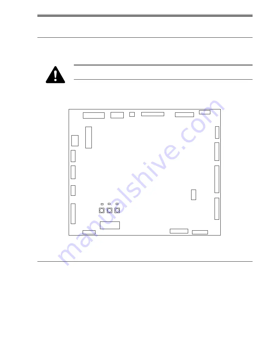
3 LEDs and Check Pins by PCB
Of the LEDs and check pins used in the machine, those needed during servicing in the field
are discussed.
Do not touch the check pins not found in the list herein. They are exclusively
for factory use, and require special tools and a high degree of accuracy.
3.1 Finisher Controller PCB
F05-301-01
SW1
6
CN17
1
LED1
PSW2
LED2
CB1
LED3
PSW1
PSW3
1
CN9
9
CN11
1
7
3
CN16
1
CN12
CN2
CN14
CN1
5
1
1
7
1
5
CN19
3
1
1
12
CN8
CN6
CN18
CN10
CN3
CN13
CN5
CN4
CN7
CN15
6
1
4
1
1
2
1
12
1
10
1
6
1
7
9
1
15
1
12
1
Switch
SW1
PSW1
PSW2
PSW3
Description
Folding position adjustment, middle 2-point stapling adjustment etc.
folding position adjustment, middle 2-point stapling adjustment etc.
folding position adjustment, middle 2-point stapling adjustment etc.
factory mode
T05-301-01
Summary of Contents for DF-75
Page 1: ...SERVICE MANUAL Published in Aug 01 5FG70760 DF 75...
Page 12: ...CHAPTER 1 GENERAL DESCRIPTION...
Page 24: ...CHAPTER 2 OUTLINE OF OPERATION...
Page 89: ...CHAPTER 3 MECHANICAL SYSTEMS...
Page 132: ...CHAPTER 4 MAINTENANCE AND INSPECTION...
Page 135: ...CHAPTER 5 TROUBLESHOOTING...
Page 142: ...5 7 CHAPTER 5 TROUBLESHOOTING...
Page 145: ...5 10 CHAPTER 5 TROUBLESHOOTING 2 1 2 Motor PCBs M7 M8 M5 M4 M3 M6 M1 M2 1 F05 201 02...
Page 175: ...5 40 CHAPTER 5 TROUBLESHOOTING...
Page 176: ...APPENDIX...
Page 180: ...A 4...
Page 184: ...A 8 APPENDIX...
Page 198: ...A 22...


