2-55
CHAPTER 2 OUTLINE OF OPERATION
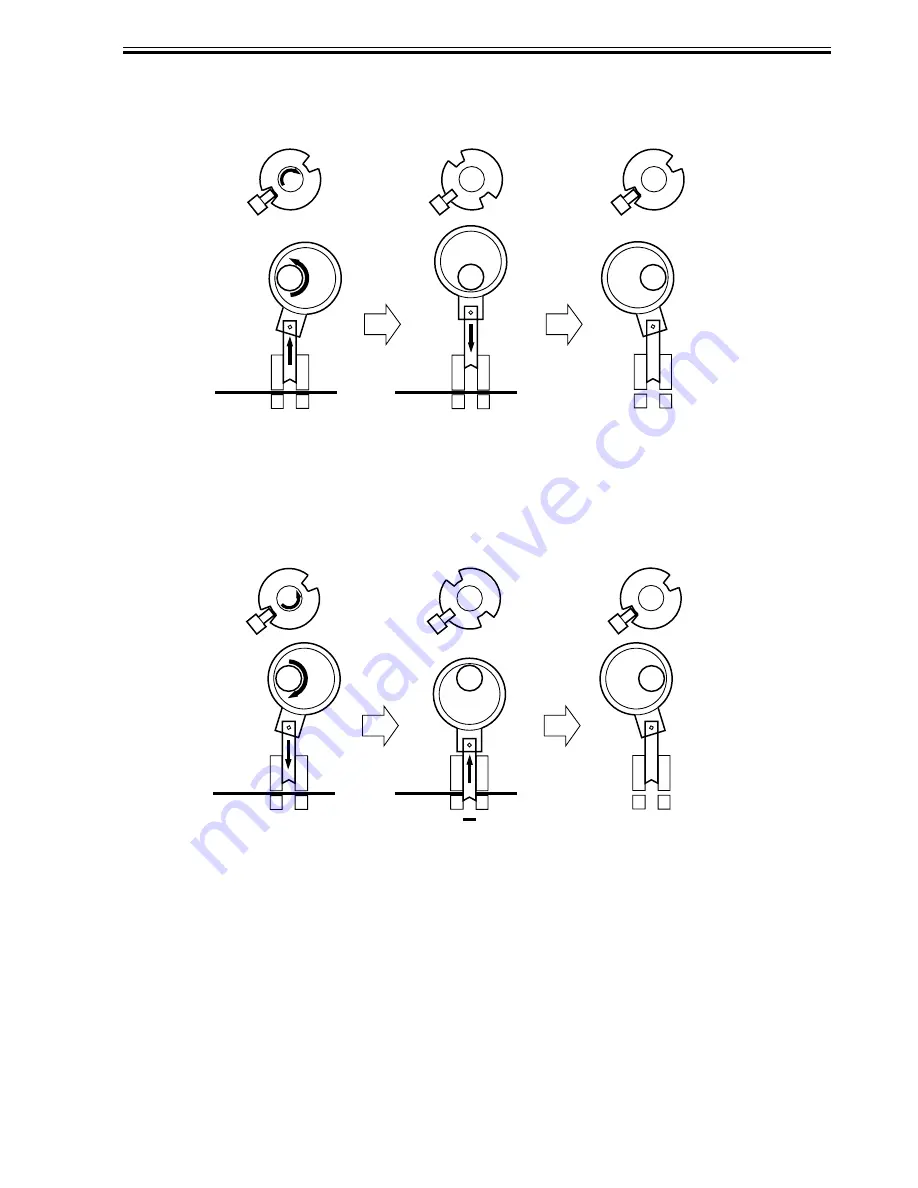
While two holes are being made, the 3-hole puncher makes a single round trip in escape di-
rection.
(punch shaft at rest/
home position)
(punch shaft CW rotation by 90˚/
punch at upper limit)
(punch shaft CW rotation by 180˚/
punch back to initial position)
F02-602-05
2) Holes are made along the trailing edge of the 2nd sheet.
(punch shaft at rest/
home position)
(punch shaft CCW rotation
by 90˚/hole made)
(punch shaft CCW rotation by 180˚/
end of punching operation)
F02-602-06
Summary of Contents for DF-75
Page 1: ...SERVICE MANUAL Published in Aug 01 5FG70760 DF 75...
Page 12: ...CHAPTER 1 GENERAL DESCRIPTION...
Page 24: ...CHAPTER 2 OUTLINE OF OPERATION...
Page 89: ...CHAPTER 3 MECHANICAL SYSTEMS...
Page 132: ...CHAPTER 4 MAINTENANCE AND INSPECTION...
Page 135: ...CHAPTER 5 TROUBLESHOOTING...
Page 142: ...5 7 CHAPTER 5 TROUBLESHOOTING...
Page 145: ...5 10 CHAPTER 5 TROUBLESHOOTING 2 1 2 Motor PCBs M7 M8 M5 M4 M3 M6 M1 M2 1 F05 201 02...
Page 175: ...5 40 CHAPTER 5 TROUBLESHOOTING...
Page 176: ...APPENDIX...
Page 180: ...A 4...
Page 184: ...A 8 APPENDIX...
Page 198: ...A 22...


