3-13
CHAPTER 3 MECHANICAL SYSTEMS
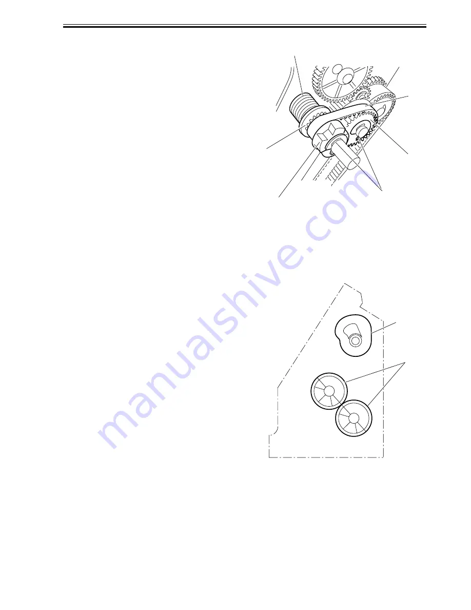
13) Remove the pin securing the gear to the
cam.
14) Assemble the spring [28], spacer [29],
staple jam releasing gear [30], timing belt
[31], and relay gear [32] and secure them
with the E-ring [33].
F03-102-13
1.2.3 Adjusting the Phase of the Gear in the Saddle Unit
If the gears at the front of the saddle unit or
the paper fold rollers in the sale unit are re-
placed or removed for some reason, adjust
the gear phase following the procedure de-
scribed below.
1) The paper fold rollers [1] and saddle cam
[2] must be positioned as shown below.
F03-102-14
[30]
[33]
[32]
[28]
[29]
[31]
[2]
[1]
Summary of Contents for DF-75
Page 1: ...SERVICE MANUAL Published in Aug 01 5FG70760 DF 75...
Page 12: ...CHAPTER 1 GENERAL DESCRIPTION...
Page 24: ...CHAPTER 2 OUTLINE OF OPERATION...
Page 89: ...CHAPTER 3 MECHANICAL SYSTEMS...
Page 132: ...CHAPTER 4 MAINTENANCE AND INSPECTION...
Page 135: ...CHAPTER 5 TROUBLESHOOTING...
Page 142: ...5 7 CHAPTER 5 TROUBLESHOOTING...
Page 145: ...5 10 CHAPTER 5 TROUBLESHOOTING 2 1 2 Motor PCBs M7 M8 M5 M4 M3 M6 M1 M2 1 F05 201 02...
Page 175: ...5 40 CHAPTER 5 TROUBLESHOOTING...
Page 176: ...APPENDIX...
Page 180: ...A 4...
Page 184: ...A 8 APPENDIX...
Page 198: ...A 22...


