2-8
CHAPTER 2 OUTLINE OF OPERATION
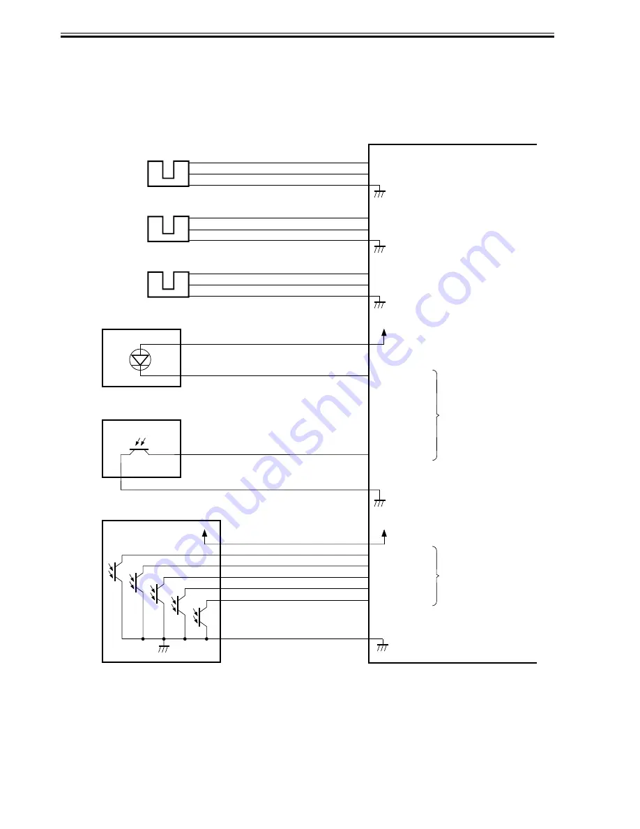
1.4 Inputs to and Outputs from the Punch Controller PCB
(option)
1.4.1 Inputs to and Outputs from the Punch Controller PCB
Punch controller PCB
PI1P
-1
J2008-3
+5 V
PUNCH
-2
-6
J1006-4
-5
SREG1*
SREG2*
SREG3*
-9
-10
-11
J1007-12
-13
SREG4*
-8
PAEND*
-7
Horizontal
registration
home position
sensor
PI3P
-1
J2009-3
+5 V
CLOCK
-2
-9
J1006-7
-8
Punch home
position sensor
+5 V
+5 V
PT1
PT2
PT3
PT4
PT5
When the hole puncher is
at home position, ‘0’.
PI2P
-1
J2007-3
+5 V
SLIDE
-2
-3
J1006-1
-2
Punch motor
clock sensor
While the punch motor
is rotating, alternates
between ‘0’ and ‘1’.
When the punch slide
unit is at home position,
‘1’.
When paper is
detected, ‘0’.
Photosensor PCB
DUSTLED
When the light is
blocked, ‘0’.
Waste full LED PCB
J1005-1
PT131
LED121
DUSTPTR
+5V
4
Waste full photosensor PCB
-2
J1005-3
F02-104-01
Summary of Contents for DF-75
Page 1: ...SERVICE MANUAL Published in Aug 01 5FG70760 DF 75...
Page 12: ...CHAPTER 1 GENERAL DESCRIPTION...
Page 24: ...CHAPTER 2 OUTLINE OF OPERATION...
Page 89: ...CHAPTER 3 MECHANICAL SYSTEMS...
Page 132: ...CHAPTER 4 MAINTENANCE AND INSPECTION...
Page 135: ...CHAPTER 5 TROUBLESHOOTING...
Page 142: ...5 7 CHAPTER 5 TROUBLESHOOTING...
Page 145: ...5 10 CHAPTER 5 TROUBLESHOOTING 2 1 2 Motor PCBs M7 M8 M5 M4 M3 M6 M1 M2 1 F05 201 02...
Page 175: ...5 40 CHAPTER 5 TROUBLESHOOTING...
Page 176: ...APPENDIX...
Page 180: ...A 4...
Page 184: ...A 8 APPENDIX...
Page 198: ...A 22...


