5-4
CHAPTER 5 TROUBLESHOOTING
ON
1
2
3
4
1.2 Electrical System (puncher unit; option)
1.2.1 Adjusting the Punch Hole Position
This mode requires operation in service mode. The range of hole displacement is between 3
and -3 in 1-mm increments. A higher setting will move the hole toward the leading edge of
sheet. (See the Service Manual of the host machine.)
1.2.2 Adjusting the Sensor Output
Perform the following when the punch controller PCB, horizontal registration sensor
(photosensor PCB/LED PCB), or waste full sensor (waste full photosensor PCB/waste full
LED PCB) has been replaced.
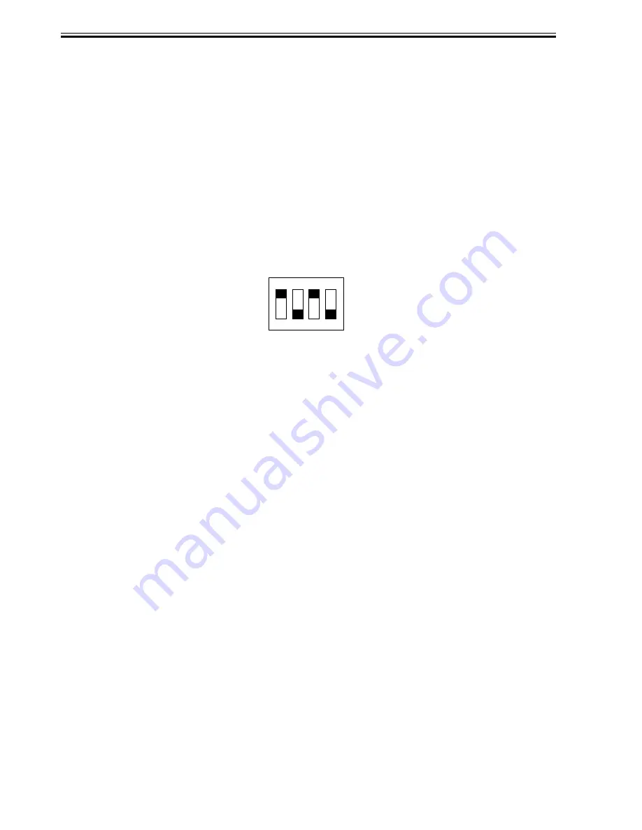
1) Shift bits 1 through 4 on the punch controller PCB as follows:
F05-102-01
2) Press SW1002 or SW1003 on the punch controller PCB. A press will automatically adjust
the sensor output.
•
The adjustment is over when all LEDs on the punch controller PCB are ON: LED1001,
LED1002, LED1003.
3) Shift all bits of DIPSW1001 to OFF.
Summary of Contents for DF-75
Page 1: ...SERVICE MANUAL Published in Aug 01 5FG70760 DF 75...
Page 12: ...CHAPTER 1 GENERAL DESCRIPTION...
Page 24: ...CHAPTER 2 OUTLINE OF OPERATION...
Page 89: ...CHAPTER 3 MECHANICAL SYSTEMS...
Page 132: ...CHAPTER 4 MAINTENANCE AND INSPECTION...
Page 135: ...CHAPTER 5 TROUBLESHOOTING...
Page 142: ...5 7 CHAPTER 5 TROUBLESHOOTING...
Page 145: ...5 10 CHAPTER 5 TROUBLESHOOTING 2 1 2 Motor PCBs M7 M8 M5 M4 M3 M6 M1 M2 1 F05 201 02...
Page 175: ...5 40 CHAPTER 5 TROUBLESHOOTING...
Page 176: ...APPENDIX...
Page 180: ...A 4...
Page 184: ...A 8 APPENDIX...
Page 198: ...A 22...


