3-12
Disassembly/Assembly
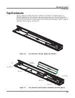
Top Enclosure
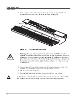
Figure 3-11
Slider Board, screw locations
8. Remove the four screws that secure the two PC board clamps (two screws per clamp).
These screws also secure the rear panel edge of the Board.
9. Remove the Slider Board.
Caution
: Each switch button cap uses a set of small pegs to mount the cap to a board. The
button caps on the Slider Board are mounted individually. If a cap becomes separated from the
board, be careful that a peg is not inadvertently broken.
Replacing the Slider Board
1. Position the Slider Board onto the top enclosure.
2. Raise the top enclosure up to verify that the switch button caps and slider shafts are
correctly positioned through their openings in the top enclosure.
3. Align the center screw hole on the front panel edge with the thread marks in the extrusion
and install the four screws that secure the front panel edge.
4. Place a PC board clamp in position. Align the center screw holes of the clamp with the
thread marks in the extrusion and install the two screws that secure the clamp. Repeat for
the other clamp.
5. Tilt the top enclosure up and install the ten slider knobs, then lay it
fl
at on your work
surface.
Caution
: To avoid damaging a slider, move the slider shaft to either the top or bottom end of its
travel to install a knob.
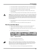
6. Connect the stranded wire cable from the Button Board on the Wheels Assembly to J304
on the Slider Board.
7. Connect the
fl
at ribbon cable from the Front Panel Board to J303 on the Slider Board.
8. If you have disconnected the cable from J302, reconnect it.
9. Follow the procedure on page 3-10 to install the Connector Board.
10. Follow the procedure on page 3-8 to install the enclosure support wall.
J303
FP Bridge
1
J302
J304
Slider
Board


