3-10
Disassembly/Assembly
Top Enclosure
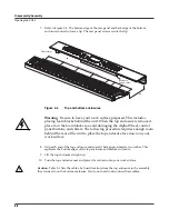
Figure 3-9
Rear panel hardware locations
6. Remove the eight screws that secure the Connector Board to the rear panel. Two screws
are longer than the others and have spacers located between the screw and the rear panel.
See Figure 3-9 for the locations of the screws and spacers.
Note
: Do not remove any other hardware from this portion of the rear panel.
7. Remove the Connector Board.
Replacing the Connector Board
Refer to Figure 3-10. The Connector Board is designed to work with a number of different
keyboards. This is determined by the position of a diode(s) on the Connector Board. There are
four diode locations, D19 through D22, located between J306 and J307 on the Connector Board.
If you are replacing the Connector Board with a new one, determine the location of the diode(s)
and be sure the new board matches the board you are removing.
Figure 3-10
Connector Board, diode con
fi
guration
1. Hold the Connector Board and position it so that the rear panel jacks, potentiometers, and
switches are correctly positioned through the rear panel portion of the top enclosure.
2. Install the eight screws that secure the Connector Board to the rear panel. Be sure to place
a spacer and use one of the longer screws at the locations noted in Figure 3-9.
longer screws with spacers
*
*
*
J306
Treble
J307
Bass
D19
D21
D22
D20
OPT
3
OPT
4
OPT
2
OPT
1


