background image

cvgt MM User Manual


Copyright © 2014 Synovatron Limited. All rights reserved. (Rev 0 February


2014

)


Summary of Contents for cvgt MM

Page 1: ...cvgt MM User Manual 1 Copyright 2014 Synovatron Limited All rights reserved Rev 0 February 2014 ...

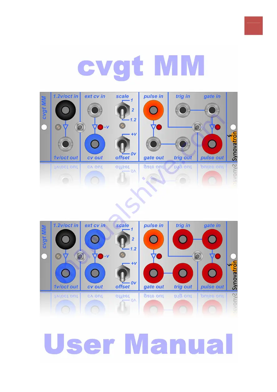
Page 2: ...nother 1V octave synthesizer The cvgt MM is available in four basic variants the 3 5mm jack socketed Eurorack and banana socketed Serge BugBrand and Fenix variants Caution Personal and equipment safety Please ensure you use the cvgt MM in accordance with these instructions especially taking great care to connect the power cable to the Model 041 Frame The power cable is keyed but always double chec...

Page 3: ... cvgt MM shown above has 3 5mm jack sockets for Eurorack connections Please be warned that connecting a Switchcraft Tini jax plug to a 3 5mm jack socket will damage the 3 5mm jack contacts as the Tini jax plug has a larger diameter Synovatron Electronic Music cannot be held responsible for any contact damage caused through incorrect connection to this module and this will invalidate your warranty ...

Page 4: ...e output range is 0V to 8 333V Variant Info A 3 5mm jack socket Eurorack compatible is shown but depending on the variant purchased could be a banana socket colour coded either blue for Serge and Fenix or red for BugBrand outputs There is a front panel accessible 10 turn trim pot that can be adjusted with a small screwdriver This is factory set to an attenuation of 0 8333 exactly It is for very fi...

Page 5: ...s switch provides an output offset that is added to the scaled input signal of either 0V 0v or 5V v In the 0v position no offset is added so a positive going input signal e g envelope will keep the output positive going v LED indicator lights if the output signal goes negative to warn that the signal is outside the useful range of 0V to 10V for the Buchla synthesizer The simplified schematics a to...

Page 6: ...cvgt MM User Manual 6 Copyright 2014 Synovatron Limited All rights reserved Rev 0 February 2014 ...

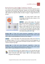
Page 7: ...cause this output to go high Refer to the example timing diagram below The LED illuminates when gate out is high Variant Info A 3 5mm jack socket Eurorack compatible is shown but depending on the variant purchased could be a banana socket colour coded either red for Serge and BugBrand or blue for Fenix outputs trig out A 0V to 10V output The output goes high 10V when the pulse in voltage is above ...

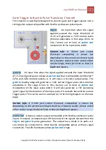
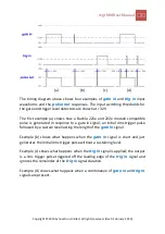
Page 8: ...trigger level detectors are shown at 2 7V and 7 7V The first example a shows the pulse shape similar to that of a Buchla 225e and 222e module pulses an initial trigger pulse followed by a sustain level which is reflected in the gate out and trig out responses Examples b c and d show that pulses are just passed through at 10V to gate out and trig out if they exceed the respective thresholds A signa...

Page 9: ...that is compatible with Buchla 225e and 222e module pulses i e it will cause a tri state output pulse The gate in leading edge will generate a 10V narrow trigger pulse also trimmer adjustable in the range 0 5ms to 5ms factory set to 4ms at pulse out irrespective of the input pulse width It will also generate a 5V sustaining gate signal for the duration of the input pulse if it extends beyond the n...

Page 10: ...se is generated in response to a gate in signal an initial 4ms trigger pulse followed by a sustain level lasting the length of the gate in signal Example b shows what happens when the gate in signal is short and just generates the initial 4ms trigger pulse without a sustaining level Example c shows what happens when the trig in signal is applied the output is a 1ms trigger pulse triggered off the ...

Page 11: ... power connector to the Model 041 frame Double check that the connector has been plugged in correctly it is keyed to prevent misconnection so it should be straightforward Fit the two 4 40 UNC screws supplied to fix the cvgt MM into the Model 041 frame nylon washers are also supplied Only fit and remove modules with the synthesizer power off and disconnected from the mains electricity supply for yo...

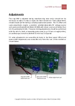
Page 12: ...et and scale adjustments require a precision settable adjustable DC voltage source and a precision Digital Multi Meter DMM with a basic accuracy of better than 0 1 preferably 0 01 The pulse timing adjustments should be performed with the aid of a clock or repeating gate source e g LFO set to roughly 10Hz an oscilloscope A small screwdriver or trim tool is required CV scale adjustments are accessib...

Page 13: ... in step 1 External CV to Buchla CV adjustment procedure 1 Set the scale switch to 1 2 and the offset switch to 0v 2 Measure cv out with a DMM and with no input connected to ext cv in record the value of the residual offset voltage reading 3 Apply 8 333V to ext cv in this should be checked with the DMM 4 Measure cv out with a DMM and adjust the scale adjustment pot for a reading of 10 000V greater...

Page 14: ...ctory set to a 4ms RV2 for a gate in leading pulse and 1ms RV1 for a trig in pulse These can however be set anywhere from 0 5ms to over 5ms as required The trig and gate pulse width timing adjustment pots RV1 and RV2 are on the rear of the module 1 Connect a clock source e g an LFO set to roughly 10Hz to trig in You should see the LED flashing 2 Connect an oscilloscope to pulse out 3 Adjust RV2 fo...

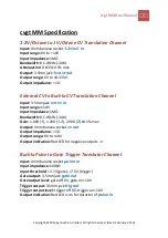
Page 15: ...nel Input 3 5mm jack ext cv in Input range 10V Input impedance 1MΩ Bandwidth DC 19kHz 3db Gain 1 000 1 1 200 1 2 2 000 2 0 1 max Output 4mm banana socket cv out Output impedance 1Ω Output range 0V to 10V Output indication Red LED for negative outputs v Buchla Pulse to Gate Trigger Translator Channel Input 4mm banana socket pulse in Input impedance 100kΩ Input threshold 2 7V gate 7 5V trigger Gate ...

Page 16: ...e pulse duration 0 5ms to 5ms is set by a trimmer factory set to 4ms Trigger initiated trigger off 0V trigger on 10V 0 5ms to 5ms initiated by trig in The leading edge of the trig in signal initiates the timer The pulse duration 0 5ms to 5ms is set by a trimmer Pulse output The gate and trigger initiated signals are OR ed together using diodes This allows other modules with diode connected outputs...

Page 17: ...l or electrical damage due to misuse or incorrect connection invalidates the warranty A low cost repair service will be available for any repairs outside of warranty conditions Quality The cvgt MM Module is a high quality professional analogue device that was lovingly and carefully designed built tested in the United Kingdom by Synovatron Electronic Music Please be assured of my commitment to prov...

Page 18: ...cvgt MM User Manual 18 Copyright 2014 Synovatron Limited All rights reserved Rev 0 February 2014 EC Declaration of Conformity in preparation ...

Reviews: