cvgt MM User Manual
14
Copyright © 2014 Synovatron Limited. All rights reserved. (Rev 0 February
2014
)
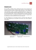
Note there is only one scale adjustment pot for the
ext cv in
channel so
the adjustment is optimised for a scale of 1.2. However due to the high
precision components used the other scale positions will track the 1.2
setting to within 0.1%.
Pulse width timing adjustment procedure
as shown below.
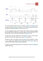
The pulse widths produced at
pulse
out
in response to
gate
in
and
trig
in
inputs are factory set to a 4ms (
RV2
) for a
gate
in
leading pulse and 1ms (
RV1
)
for a
trig
in
pulse. These can however be set anywhere from 0.5ms to over 5ms
as required. The trig and gate pulse width timing adjustment pots
RV1
and
RV2
are on the rear of the module.
(1) Connect a clock source, e.g. an LFO, set to roughly 10Hz to
trig in
. You
should see the LED flashing.
(2) Connect an oscilloscope to
pulse
out
.
(3) Adjust
RV2
for the desired pulse width of the 10V trigger pulse at
pulse out
in response to
trig in
.
(4) Move the clock source to gate in.
(5) Adjust
RV1
for the desired pulse width of the 10V leading pulse, not the 5V
gate portion, at
pulse out
in response to
gate in
.
This completes the adjustments


