background image

4-10

Troubleshooting & Maintenance

Replacing the Battery

Replacing the Battery

The PC3x uses a 

fl

at three volt Lithium coincell battery to power the clock. When the battery 

voltage runs low, the unit boots up with a low battery message.

Note

:  The battery voltage can be checked at anytime using the Scanner Diagnostics. See 

page 4-11 for more information.

Accessing the Battery

1. Place the PC3x upside down on a 

fl

at protected surface.

2. Remove the seven screws that secure the access panel and set it safely aside.

Removing the Battery

The battery (CR2032) in the PC3x keyboard is mounted into a holder on the Engine Board and is 

accessible when the access panel is removed.

1. Insert a 

fl

at plastic tool (plastic knife, pen cap, etc.) into one of the openings between the 

battery and the holder to lift the battery.

Figure 4-1

Battery and holder

2. Ease the battery out of the holder. If necessary, insert the plastic tool at the bottom of the 

holder (closest to the Engine Board) to remove the battery.

Installing the Battery

Caution

:  Danger of explosion if battery is incorrectly replaced. Replace only with the same or 

equivalent type (CR2032).

1. Position the battery over the holder so that the positive terminal is pointing to the 

Expansion ROM sockets.

2. Slide the battery into the holder and apply slight pressure until it snaps into place.

3. Position the access panel on the bottom enclosure and install the seven


screws to secure it.

Insert the tool here
to lift the battery.

Insert the tool between
the holder and the battery 
to ease the battery out
of the holder.

CR2032

Summary of Contents for PC3x

Page 1: ...ng Co Ltd Young Chang Kurzweil and PC3 are trademarks of Young Chang Co Ltd All other products and brand names are trademarks or registered trademarks of their respective companies Product features an...

Page 2: ...ed service personnel when A The power supply cord or the plug has been damaged B Objects have fallen onto or liquid has been spilled into the product C The product has been exposed to rain D The produ...

Page 3: ...y use attachments accessories specified by the manufacturer 12 Use only with a cart stand tripod bracket or table specified by the manufacturer or sold with the apparatus When a cart is used use cauti...

Page 4: ...zweil Music Systems 19060 S Dominies Hills Drive Rancho Dominguez California 90220 USA Telephone 310 637 2000 Fax 310 637 2025 http www kurzweilmusicsystems com Kurzweil Co LTD iPark Building 102 Floo...

Page 5: ...Expansion DIMM Check 2 5 MIDI UART 2 5 External Card 2 6 MARA Delay RAM 2 6 MARA Sound ROM 2 6 Audio Output 2 7 Diagnostic Version 0 20 or earlier 2 7 Sine Wave Test 2 8 Chapter 3 Disassembly Assembl...

Page 6: ...the Keyboard Contact Boards 3 24 Removing the Treble Contact Board 3 24 Replacing the Treble Contact Board 3 24 Removing the Bass Contact Board 3 24 Replacing the Bass Contact Board 3 25 Connecting t...

Page 7: ...4 Front Panel Problems 4 15 LCD not lit 4 15 LCD lit no characters 4 15 Buttons Sliders or Controllers not working 4 15 Keyboard Problems 4 16 Dead Keyboard 4 16 Dead Note s or no velocity sensitivity...

Page 8: ...Assembly Aux and Headphone Outs 8 of 9 6 10 Engine Board Assembly Mictors CPLD Power 9 of 9 6 11 Connector Board M38869 Scanner 1 of 4 6 12 Connector Board MIDI Pedals Ribbon LCD Contrast 2 of 4 6 13...

Page 9: ...point out specific instructions but also alert you to variations between manufactured units A brief description of these symbols follows Note Provides additional information indicates differences betw...

Page 10: ...s Two 1 4 jacks to connect pedals that can be assigned to control operations such as volume expression etc use 10K linear taper potentiometer 1 4 tip ring sleeve wiper to tip Breath Input A 3 5mm jack...

Page 11: ...ach slider for KB3 mode and below when used for data and MIDI controllers Figure 1 4 Mode Edit Chan Layer and record function buttons Mode buttons use these buttons to select one of the eight availabl...

Page 12: ...buttons to select an action or item shown directly above the button in the bottom line of the display Cursor buttons use these buttons navigate the cursor in the display Exit button press this button...

Page 13: ...se and lowercase numbers and spaces Pressing these buttons simultaneously selects the Panic button Select the Panic button to send an All Notes All Controllers Off message on all 16 channels Storage A...

Page 14: ...1 6 Introduction PC3x Front Panel...

Page 15: ...Card MARA Delay RAM MARA Sound ROM Audio Output Warning If possible save all user programs and setups before entering diagnostics or performing maintenance or repair For instructions refer to Saving...

Page 16: ...tions and test results Press the Left Right Up or Down cursor buttons or turn the Alpha Wheel to navigate through the available tests Use the soft buttons located below the LCD to select different tes...

Page 17: ...exit diagnostics press the Exit button to return to the Boot Loader Loop Loop continuously runs an individual test The number of tests performed and the result is displayed continuously in the LCD Th...

Page 18: ...s manual many references are made to the MARA 1 and MARA 2 ICs For service personnel unfamiliar with the PC3x MARA is the name given to the two Kurzweil Custom Sound ICs This tests verifies the proper...

Page 19: ...ith the DIMM s their installation soldering of the socket s or related circuitry on the Engine Board MIDI UART The MIDI test performs a loop back of the serial port by sending a 23 byte pattern over t...

Page 20: ...iffers greatly from the value Wrote it could mean there was an address bit error or one or more of the control signals are bad A failure of this test would indicate a problem with the DDR SDRAM U13 MA...

Page 21: ...diagnostic Version 0 19 or earlier to check amplitude polarity and frequency response flatness an oscilloscope is needed 1 Move the Volume slider to maximum then press the Play Sawtooth soft button 2...

Page 22: ...1 9 to minimum 2 Use the numeric keypad and select program 1000 Sine Wave 3 Press the SW1 button located directly above the Mod Wheel 4 Play C4 Middle C to produce a 261 Hz sine wave at all of the ou...

Page 23: ...25 Vrms 6 00Vp p 14 8 dBm unbalanced 20 8 dBm balanced at the Main and Aux Outputs 3 The Headphones Output level is twice that of the Line Outputs Clipping is approximately 7 0 Vrms or 20 0Vp p 4 The...

Page 24: ...2 10 Diagnostics Description of Tests...

Page 25: ...es Connectors Cables All cables with connectors are keyed and therefore cannot be reversed Warning Some units may have a small PC board installed on the flat ribbon cable connected to J202 on the Fron...

Page 26: ...ur work surface 3 Move the unit so that the rear panel portion of the unit hangs over the edge of your work surface This gives you access to the eight screws that secure the rear panel portion of the...

Page 27: ...3 Refer to Figure 3 1 Move the unit so that one end hangs over the edge of your work surface 4 Remove the endcap locking bracket screw from the bottom enclosure Caution When you remove the endcap lock...

Page 28: ...nd sliders The following procedure requires enough room behind the rear of the unit to place the top enclosure face down on your work surface 8 Grip each end of the top enclosure and rotate it back ap...

Page 29: ...one end of the rear panel edge hangs over the edge of your work surface and install the rear panel screw at that end Slide the unit back onto your work surface Repeat for other end Warning Perform Ste...

Page 30: ...the endcap locking bracket is in position it rests against the endcap clamping bracket located on the underside of the top enclosure See Figure 3 5 Figure 3 5 Top enclosure endcap locking and clampin...

Page 31: ...top enclosure Figure 3 6 shows the placement of the enclosure support wall on the top enclosure Figure 3 7 shows the placement of the boards transformer and AC recptacle with the enclosure support wa...

Page 32: ...d 2 Disconnect the cable bundle from J302 on the Connector Board and move the cable bundle away from the enclosure support wall 3 Remove the seven screws that secure the enclosure support wall to the...

Page 33: ...4 Disconnect the flat ribbon cables from J304 J306 and J307 Figure 3 8 Cable locations 5 Disconnect the stranded wire cables from J305 J308 and J324 Ref Name Cable Type Destination J301 PC3 Power stra...

Page 34: ...n of a diode s on the Connector Board There are four diode locations D19 through D22 located between J306 and J307 on the Connector Board If you are replacing the Connector Board with a new one determ...

Page 35: ...stranded wire cables from the Engine Board to J301 J303 and J325 on the Connector Board 9 Follow the procedure on page 3 8 to install the enclosure support wall Removing the Slider Board 1 Follow the...

Page 36: ...panel edge with the thread marks in the extrusion and install the four screws that secure the front panel edge 4 Place a PC board clamp in position Align the center screw holes of the clamp with the t...

Page 37: ...bezel that is secured to the Front Panel Board Remove the four screws that secure the LCD to the front panel bezel Figure 3 12 J203 1 and J203 2 connections on Front Panel Board 5 Refer to Figure 5 A...

Page 38: ...oard 3 Table 3 4 lists the cables connected to the Front Panel Board Note If the service you are performing only requires that you have access to the Front Panel Board for component testing or compone...

Page 39: ...nt Panel Board You have already removed the enclosure support wall but one screw remains securing this edge of the board See Figure 3 13 and remove the remaining screw 7 Remove the six screws that sec...

Page 40: ...amp with the thread marks in the extrusion and install the two screws that secure the clamp Repeat for the other two clamps 3 Install the screw that secures the front panel edge See Figure 3 13 4 If y...

Page 41: ...at secure the front panel edge of the Engine Board Figure 3 14 Engine Board screw locations 7 Remove the two screws that secure the PC board clamp and rear panel edge of the Engine Board to the top en...

Page 42: ...J21 and J33 on the Engine Board 6 Connect the shielded wire cable from the Connector Board to J18 on the Engine Board Removing the USB xD Daughtercard The USB xD Daughtercard is mounted on the Engine...

Page 43: ...board back pressure black key 4 Disconnect the stranded wire cable from J201 on the Wheels Board 5 Disconnect the stranded wire cable from J304 on the Slider Board 6 Remove the Wheels Assembly Replaci...

Page 44: ...your work surface so that you can access the four screws and washers securing the Wheels Assembly to the bottom enclosure Remove the four screws and washers Figure 3 15 PC3x keyboard bottom 6 Slide th...

Page 45: ...tape Be sure that the small ribbon cable connecting the Bass and Treble Contact Boards is connected 2 Connect the flat ribbon cables to J306 and J307 on the Connector Board 3 Secure the flat ribbon ca...

Page 46: ...toward the rear panel to give you enough access to remove and replace keys 2 The following diagrams illustrate the outlines of the natural and sharp keys and the location and functions of the compone...

Page 47: ...ous procedure 2 Unlock the key from the pivot anchoring the key to the keyboard chassis To do this insert a small flat screwdriver at the bottom of the pivot and press toward the front edge of the key...

Page 48: ...ce Be sure that the keys are resting on a soft surface to avoid scratching or other damage The stiffening brackets and Treble and Bass Contact Boards are now visible Removing the Treble Contact Board...

Page 49: ...and Treble Keyboard Contact Boards 3 Examine the keyboard contact strips and look at the design of an individual contact The top portion of the contact has two indentations One indentation is deeper...

Page 50: ...3 26 Disassembly Assembly PC3x Keyboard Assembly...

Page 51: ...en disconnecting cables always peel back the tape from one side so that the tape remains properly positioned Surface Mount Devices The removal and replacement of surface mount devices requires trainin...

Page 52: ...es the unit to factory default settings File Utilities Use this to select one of the following functions format an xD card save and restore PC3x files or execute a PC3x image from an xD card or USB fi...

Page 53: ...press the Select soft button An asterisk to the left of the file name indicates the selected file Use the Right or Left cursor buttons to highlight Range Bank and turn the Alpha Wheel to scroll down t...

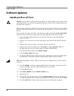
Page 54: ...move the xD card and insert it into the xD card slot on the PC3x 4 Apply power to the unit When the Welcome to the Kurzweil PC3 message appears in the LCD quickly press and release the Exit button 5 F...

Page 55: ...the latest software version Note Be sure to always read the downloaded release notes and installation instructions in case they have changed since this manual was written 5 From the PC3x Boot Loader s...

Page 56: ...unit to factory settings The following assumes that you are familiar with the procedures to enter the Boot Loader and perform normal system updates using an xD Card or the USB port via computer 1 1 Us...

Page 57: ...t on the PC3x 2 Apply power to the unit When the Welcome to the Kurzweil PC3 message appears in the LCD quickly press and release the Exit button 3 Check the computer desktop and verify that the Kurzw...

Page 58: ...conds 11 The top line should now display Choose a diags executable file Select the Diagnostics file then press the CHOOSE soft button Installation will take only a second or two A message Bootable sys...

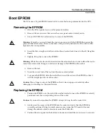
Page 59: ...e tool to move from side to side Doing so could cause damage to the EPROM or the socket 6 Remove the tool 7 Insert the curved end of the tool into the same extraction hole 8 To remove the EPROM slide...

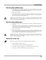
Page 60: ...flat plastic tool plastic knife pen cap etc into one of the openings between the battery and the holder to lift the battery Figure 4 1 Battery and holder 2 Ease the battery out of the holder If necess...

Page 61: ...LCD example PC3x scanner tests The first line of the display shows the scanner software version the battery voltage the current value for the Pitch Wheel position and the keyboard configuration The se...

Page 62: ...f the normal test results for the Slider A follows your results may vary slightly At bottom SLIDER 1 0 At center SLIDER 1 128 At top SLIDER 1 255 Right Main Output Insert a 1 4 plug or cable into the...

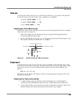
Page 63: ...4 3 Bottom enclosure trimpot locations Keyboard To test the keyboard press any key The key name and number will be displayed twice in the LCD The first set of name and number is the test result for th...

Page 64: ...9 of the Engine Board schematics see page 6 11 in Chapter 6 Verify the voltages at the connector Pin 1 ground Pin 2 5 volts Pin 3 12 volts Pin 5 12 volts 7 Open the unit 8 Disconnect the stranded wire...

Page 65: ...it is seated properly If necessary disconnect and reseat it 5 Open the unit 6 Check solder connections on the LCD and Engine Boards 7 Refer to the Engine Board schematics see page 6 8 in Chapter 6 Ch...

Page 66: ...maged 3 Disconnect and reseat the cables 4 Refer to the Connector Board schematics 5 Check U1 IC Scanner M38869 on the Connector Board for keyboard signals 6 Trace signal path 7 Find and replace bad c...

Page 67: ...XFMR LCD PC3 Power J15 J5 J21 Expansion Sound ROM J11 Bank 1 J10 Bank 0 Expansion Sound ROM MIDI CPU Dig Audio Out Audio Out Graphic LCD J18 USB SM Card J33 J12 Connector Board J301 PC3 Power J303 MID...

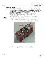
Page 68: ...fuse holder is located on the rear panel and is part of the power entry module 3 The outer cover for the power switch and the fuse holder is a hinged door 4 Insert at an angle a thin flat tool into t...

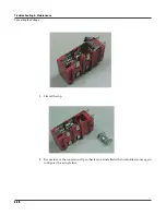
Page 69: ...Two fuses may be used in the USA if the conversion clip is removed See the photos and instructions that follow to remove the conversion clip The fuse sizes may be either 1 25 X 0 25 or 5 mm X 20 mm Fo...

Page 70: ...20 Troubleshooting Maintenance Converting the Voltage 3 Lift off the clip 4 Be sure to save the conversion clip so that it can be installed if the fuse holder is once again configured for a single fus...

Page 71: ...20 mm fuse Replacing the Fuse Holder 1 Insert the fuse holder into the power entry module The indicator showing the desired voltage should be positioned toward the outer edge of the module away from...

Page 72: ...4 22 Troubleshooting Maintenance Converting the Voltage...

Reviews: