3-8
Disassembly/Assembly
Top Enclosure
Removing the Enclosure Support Wall
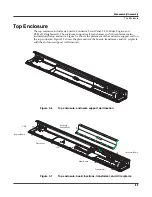
The shielded cable bundle connecting J302 on the Connector Board to J18 on the Engine Board is
routed and taped along the front of the enclosure support wall. Tape also secures the cable
bundle to the Slider and Front Panel Boards. Always peel back the tape from one side so that the
tape remains properly positioned.
Note
: The routing of this cable is important to minimize noise and hum. Be sure to note the
placement of the cable so that you position it properly when you reinstall the enclosure support
wall.
1. Peel back the tape from one side to free the cable bundle from the enclosure support wall
and the Slider Board.
2. Disconnect the cable bundle from J302 on the Connector Board and move the cable bundle
away from the enclosure support wall.
3. Remove the seven screws that secure the enclosure support wall to the top enclosure, and
remove the enclosure support wall.
Replacing the Enclosure Support Wall
1. Align the center screw holes of the three-hole groupings in the enclosure support wall
with the thread marks in the extrusion.
2. Install the seven screws that secure the enclosure support wall to the top enclosure.
3. Secure the cable bundle to the front of the enclosure support wall with the tape.
4. Connect the shielded cable bundle to J302 on the Connector Board and secure it to the
Slider Board with the tape.
Note
: The routing of this cable is important to minimize noise and hum. Be sure to note the
placement of the cable so that you position it properly when you reinstall the enclosure support
wall.


