Parameter Description
Settings
Factory setting
3-9-1-1
PI mode
Disabled
Disabled
3-9-1-6
PI Auto
Deactivated
Activated
Maintain the following sequence for deactivating the process controller:
1.
Change parameter
3-9-1-6
.
2.
Change parameter
3-9-1-1
.
⇨
Parameter
1-3-1-3
Setpoint displays the current setpoint.
If the control panel was used to specify a setpoint (
3-5-2-1
Configurable Setpoint and
adaptation of setpoint sources
3-5-4-1
to
3-5-4-3
), for example, this setpoint is
increased or decreased via a digital potentiometer function.
7.1.1.4
Closed-loop control mode
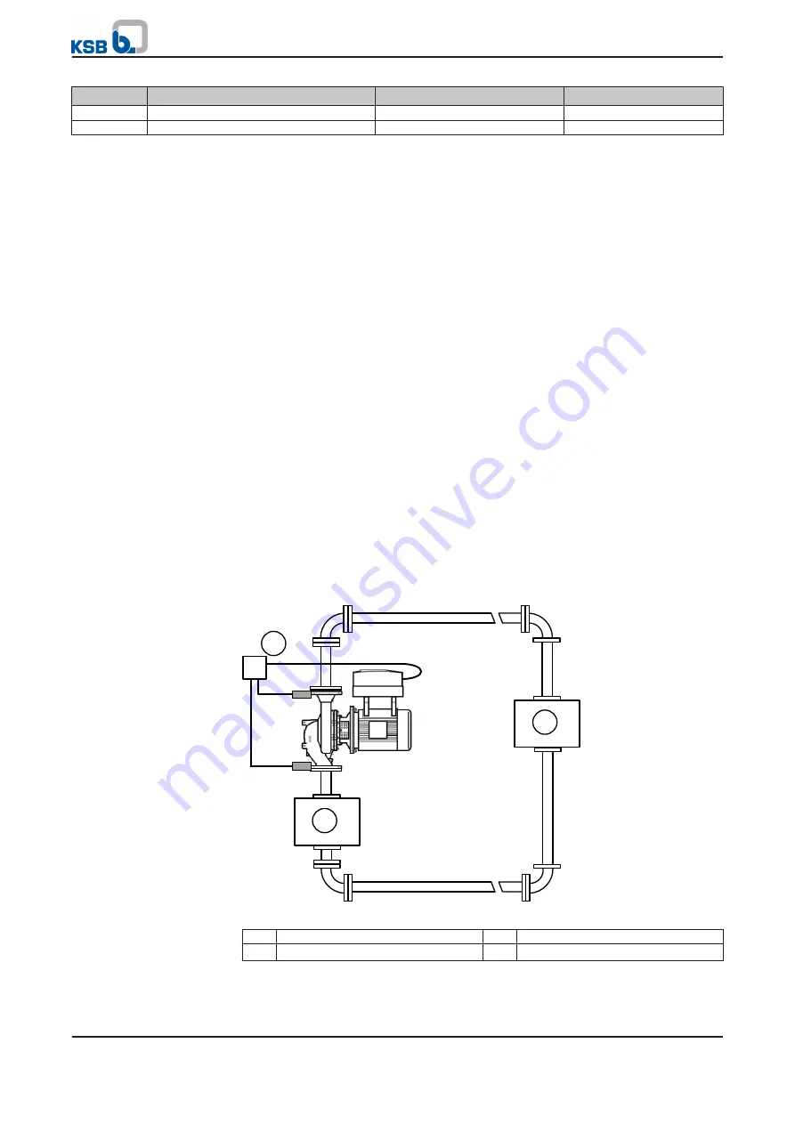
PumpDrive features an integrated process controller (PI controller). An external
sensor supplies the controller with the actual value (feedback) signal from the
process. Current changes in consumption are identified by comparison with the
setpoint and then compensated by adjusting the speed.
PumpDrive has been set at the factory so that it will automatically recognise a sensor
connected to analog input 2 and will then automatically activate closed-loop control
mode in the following cases:
▪
A sensor has been connected to analog input 2 and has been recognised:
– Analog input 2 for connection to control terminals P7: 6/7 (
– Analog input 2 for connection to power supply and motor connections,
By default, the setpoint is read at analog input 1 (0 - 10 V standard signal). All units
and setting ranges are converted to percentages (%), while the setpoints and actual
values can be displayed in a different unit.
In closed-loop control mode, digital input 1 (terminal strip P4:14) has to be connected
to the 24 V DC supply (terminal strip P4:13). If digital input 1 has +24 V DC applied to
it and PumpDrive is set to automatic mode, PumpDrive will start.
1
2
Δ
p
3
Fig. 27: Closed-loop control mode example
1
Heat generator
2
Consumer
3
Differential pressure sensor
7 Commissioning/shutdown
54 of 162
PumpDrive


