


7
TECHNICAL DATA
80
OPTISYS SLM 2100
www.krohne.com
01/2017 - 4002737304 - MA OPTISYS SLM 2100 R04 en
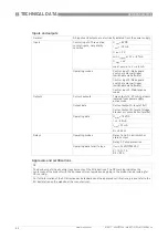
Inputs and outputs
General
All inputs and outputs are electrically isolated from the power supply.
Inputs
Control inputs: Three active
control inputs, not polarity
sensitive
U
out
= 8 VDC
I
out
= -10 mA
U
low
≤
2 V
min I
typical
at 2 V = -8.7 mA
U
high
≥
4 V
max I
typical
at 4 V = -6.8 mA
Operating modes
Control input 1: Rake guard
switch or external trigger
(switchable via Software)
Control input 2: Rake guard
switch or external trigger
(switchable via Software)
Control input 3: Maintenance
mode
Outputs
Current outputs
Two outputs (4...20 mA), galvanic
isolated from power supply,
active mode
Output data
Current output A: level of fluff
Current output B: level of sludge
blanket or concentration (profile)
Operating data
U
max
= 18 VDC
I = 4...20 mA
I
max
≤
22 mA
R
L
≤
550
Ω
Relays
Operating modes
Relay 1 and 2: Limit switch or
status output
Relay 3: Pump protection
Operating data for all relays
U
ext
≤
24 VDC/250 VAC
K1 / K2
≤
1 A
K3
≤
0.3 A
Approvals and certifications
CE
The device meets the essential requirements of the EU directives. The CE marking indicates the
conformity of the product with the European Union legislation applying to the product and providing for
CE marking.
For full information of the EU directives and standards and the approved certifications, please refer to the
EU declaration on the website of the manufacturer.
Summary of Contents for OPTISYS SLM 2100
Page 85: ...NOTES 8 85 OPTISYS SLM 2100 www krohne com 01 2017 4002737304 MA OPTISYS SLM 2100 R04 en ...
Page 86: ...8 NOTES 86 OPTISYS SLM 2100 www krohne com 01 2017 4002737304 MA OPTISYS SLM 2100 R04 en ...
Page 87: ...NOTES 8 87 OPTISYS SLM 2100 www krohne com 01 2017 4002737304 MA OPTISYS SLM 2100 R04 en ...