


ELECTRICAL CONNECTIONS
4
41
OPTISYS SLM 2100
www.krohne.com
01/2017 - 4002737304 - MA OPTISYS SLM 2100 R04 en
4.10.1 Connection of the relays
The terminals for the connection of the two relays (K1 & K2) are located on the mainboard.
Please refer to the following diagram for proper connection of the cables.
DANGER!
Never connect an external water pump directly to the sludge level meter connector K3, the
output connector is only specified as a control output for a motor protection.
DANGER!
All work on the electrical connections may only be carried out with the power disconnected.
INFORMATION!
Assembly materials and tools are not part of the delivery. Use the assembly materials and tools
in compliance with the applicable occupational health and safety directives.
INFORMATION!
The correct connection of the relays may only be ensured by using signal cables which are
approved for the rated current and voltage.
INFORMATION!
All cables must have a test voltage of min. 2 kV and an appropriate outer insulation (additional to
the insulation of the individual wire). The outer insulation should be removed 40 mm / 1.57". The
minimum cross section of the wires is 1.5 mm
2
/ 16 AWG and the maximum is 2.5 mm
2
/ 12 AWG.
INFORMATION!
In order to assure proper sealing of the cable feedthrough only cables with a diameter between
6...12 mm / 0.24...0.47 inch should be used.
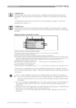
Figure 4-8: Connection diagram of relays K1 and K2
1
LED
2
Voltage source
Summary of Contents for OPTISYS SLM 2100
Page 85: ...NOTES 8 85 OPTISYS SLM 2100 www krohne com 01 2017 4002737304 MA OPTISYS SLM 2100 R04 en ...
Page 86: ...8 NOTES 86 OPTISYS SLM 2100 www krohne com 01 2017 4002737304 MA OPTISYS SLM 2100 R04 en ...
Page 87: ...NOTES 8 87 OPTISYS SLM 2100 www krohne com 01 2017 4002737304 MA OPTISYS SLM 2100 R04 en ...