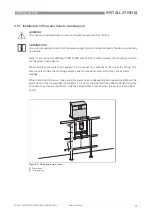


ELECTRICAL CONNECTIONS
4
39
OPTISYS SLM 2100
www.krohne.com
01/2017 - 4002737304 - MA OPTISYS SLM 2100 R04 en
The terminals for the connection of the three control inputs are located on the mainboard.
Please refer to the following diagram for proper connection of the cables.
Connecting the control inputs
•
Open the cable drum and electronic compartment door.
•
Push the prepared cables through the cable feedthrough and route them to the electronic
compartment (for more information refer to
Overview of cable connections
on page 30).
•
Connect the positive and negative lead according to the connection diagrams above.
•
Connect the shield to one side only e.g. on PCS (process control system) side.
•
Tighten the screw connection of the cable feedthrough securely.
•
Seal all cable feedthroughs that are not needed with a plug.
•
Close both compartment doors.
Figure 4-6: Control input
1
Signal
Figure 4-7: Connection control input
1
Control input (CI1)
2
Control input (CI2)
3
Control input (CI3)
INFORMATION!
In order to assure proper sealing of the cable feedthrough only cables with a diameter between
6...12 mm / 0.24...0.47 inch should be used.
Summary of Contents for OPTISYS SLM 2100
Page 85: ...NOTES 8 85 OPTISYS SLM 2100 www krohne com 01 2017 4002737304 MA OPTISYS SLM 2100 R04 en ...
Page 86: ...8 NOTES 86 OPTISYS SLM 2100 www krohne com 01 2017 4002737304 MA OPTISYS SLM 2100 R04 en ...
Page 87: ...NOTES 8 87 OPTISYS SLM 2100 www krohne com 01 2017 4002737304 MA OPTISYS SLM 2100 R04 en ...