


2
DEVICE DESCRIPTION
12
OPTISYS SLM 2100
www.krohne.com
01/2017 - 4002737304 - MA OPTISYS SLM 2100 R04 en
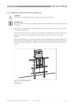
2.2 Device description
Main electronics unit
The main electronic unit is located in a separate compartment above the cable drum, which can
be accessed via a separate door with a key lock. It contains the mainboard and fan assembly. The
mainboard bears the main processor and all electrical connectors. It also controls all
mechanical and electrical events in the device and communicates with sensor, display and
keyboard. It additionally contains the current outputs and control inputs.
Fan assembly
The position of the fan is on the top right side of the enclosure. In combination with the heater
the instrument maintains suitable temperature conditions inside the enclosure of the meter.
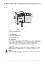
Figure 2-2: Device description of OPTISYS SLM 2100
1
Fan
2
Electronic compartment door with display
3
Cable drum compartment door
4
Guide roller and zero point reference switch
5
Sensor
6
4 x cable feedthrough M20
7
Cable drum with heating unit at the back
8
Pickup and axle board with optical interface
9
Safety switch
10
Main electronics and connectors
DANGER!
The rotating fan blades can be accessed, when the electronic compartment door is open and
there is a risk of injury when rotating fan is touched.
Summary of Contents for OPTISYS SLM 2100
Page 85: ...NOTES 8 85 OPTISYS SLM 2100 www krohne com 01 2017 4002737304 MA OPTISYS SLM 2100 R04 en ...
Page 86: ...8 NOTES 86 OPTISYS SLM 2100 www krohne com 01 2017 4002737304 MA OPTISYS SLM 2100 R04 en ...
Page 87: ...NOTES 8 87 OPTISYS SLM 2100 www krohne com 01 2017 4002737304 MA OPTISYS SLM 2100 R04 en ...