background image

3 .2   Examination Flow

95

Chapter 3

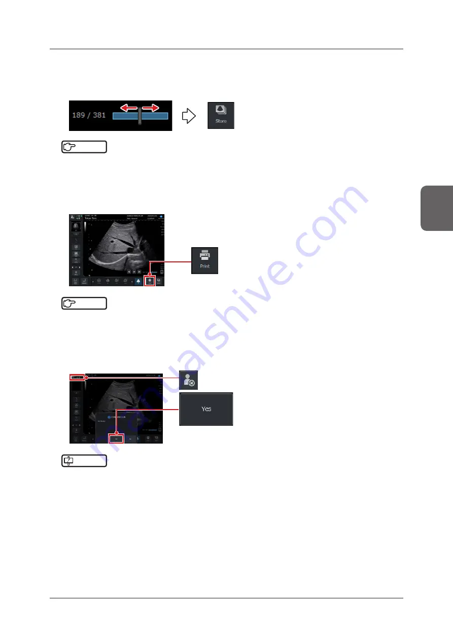
Select and store an image using the Cine function .

•  When the Cine bar in the lower right corner of the image display area has been displayed, you can play back 

a desired frame by moving the trackball right and left . When you have selected your desired image, press the 

[Store] button in the lower right corner of the study screen .

Reference

 •••••••••••••••••••••••••••••••••••••••••••••••••••••••••••••••••••••••••••••••••••••••••••••••••••••

•  For the Cine function, refer to "5 .1 Cine" .
•  For storing a still image, refer to "6 .1 .1 Storing Still Images" .

 •••••••••••••••••••••••••••••••••••••••••••••••••••••••••••••••••••••••••••••••••••••••••••••••••••••••••••••••••••••

Print an image .

•  Press the [Print] button in the lower right corner of the study screen .

Reference

 •••••••••••••••••••••••••••••••••••••••••••••••••••••••••••••••••••••••••••••••••••••••••••••••••••••

•  There are two types of printing button . Refer to "6 .3 Printing Images" .

 •••••••••••••••••••••••••••••••••••••••••••••••••••••••••••••••••••••••••••••••••••••••••••••••••••••••••••••••••••••

End the examination .

•  Press the [Study] button on either the [Patient] screen or the study screen .

• 

The confirmation dialog box to end examination is displayed. Press [Yes] to end the examination.

IMPORTANT

 •••••••••••••••••••••••••••••••••••••••••••••••••••••••••••••••••••••••••••••••••••••••••••••••••••••

•  Be sure to end the examination before putting the system into a Shutdown / Standby mode .

 •••••••••••••••••••••••••••••••••••••••••••••••••••••••••••••••••••••••••••••••••••••••••••••••••••••••••••••••••••••

Summary of Contents for SONIMAGE HS2

Page 1: ...EN 01...

Page 2: ......

Page 3: ...nel Rear Panel 57 1 6 5 Monitor 59 1 6 6 Compatible Peripheral Devices 63 1 6 7 Connectable Transducers and Biopsy Brackets 65 1 6 8 List of Optional Items 66 Chapter 2 Before Examination 69 2 1 Insta...

Page 4: ...mon Function in Ultrasound Images 181 5 1 Cine 182 5 1 1 Cine Playback 182 5 1 2 Cine Operation 183 5 1 3 Cine Pop up Menu 183 5 1 4 Cine Clip Store 184 5 2 Body Mark 185 5 2 1 Body Mark Menu 185 5 2...

Page 5: ...SNV Pop up Menu 262 8 2 8 Selection of Biopsy Bracket 264 8 3 Acoustic Standoff 265 8 3 1 Safety Precautions Warnings for Acoustic Standoff 265 8 3 2 Usage 266 8 3 3 Cleaning and Disinfection of Acou...

Page 6: ...6...

Page 7: ...7 Introduction...

Page 8: ...the measurement result obtained from each application by measurement data To help a user acquires optimal images the system is preset before shipping Normally it will be unnecessary for a user to mak...

Page 9: ...A flow of operations basic operations frequently used functions etc are excerpted For details refer to the Opera tion Manual Fundamentals and Operation Manual Applications z z Notes on safety Describe...

Page 10: ...oes not always start on the top study screen is used to show which button or option on the top screen a user should select to switch to the target screen Example For an operating procedure to be start...

Page 11: ...ademarks or registered trade marks of corresponding companies CAB32 DLL Copyright 1998 2002 K Miyauchi This library is based in part on the Microsoft Cabinet Software Development Kit VS FlexGrid Copyr...

Page 12: ...ccur Safety Precautions Warnings z z There are DANGERs WARNINGs and CAU TIONs at following pages DANGER 1 1 Intended Use 8 1 1 Safety Precautions Warnings for Trans ducer 8 3 1 Safety Precautions Warn...

Page 13: ...products This device may only be used in combination with software confirmed to be safe and compatible and installed according to predetermined installation procedures The application of the latest se...

Page 14: ...ity measures within the facility using this de vice and other facilities connected to the facility via networks Isolate the device from the connected network immediately upon infection by malware conc...

Page 15: ...formation about labels is described in Description of symbols and the labels correspond to the numbers in the fol lowing figure Read the Operation Manual carefully before using the system Location app...

Page 16: ...side of the main unit GS1 01 21 0197 2 Windows label Affix on the back side of the main unit 3 WARNING CAUTION label 4 Hot surface label Affix on the back side of the main unit Transducer Option No La...

Page 17: ...iption 6 Label of origin Affix on the back side of the tray This marking can be read from the bottom part of the Pole Cart2 7 CAUTION label 8 System total weight label Maximum total mass of the system...

Page 18: ...el 12 CAUTION label 13 PSE label Power Extension Unit2 CW kit Option No Label Description 14 Label of origin Affix on the back side of the main unit SONIMAGE HS1 CW Kit SONIMAGE HS1 CW Foot Switch Dua...

Page 19: ...Switch Triple Option No Label Description 16 Label of origin SONIMAGE HS1 Foot Switch Triple SONIMAGE HS1 Battery 17 18 20 19 No Label Description 17 WARNING label 18 Label of origin 19 Label RoHS 20...

Page 20: ...e unit Option 22 Printed on the surface 21 No Label Description 21 Label of origin SONIMAGE HS1 Three Port Probe Unit SONIMAGE HS1 Reference Signal Unit Option 23 26 25 24 No Label Description 23 Part...

Page 21: ...21 Labels No Label Description 25 Rating label 26 Label of origin Keyboard kit Option 27 No Label Description 27 Label of origin WARNING label SONIMAGE HS1 Keyboard Kit SONIMAGE HS1...

Page 22: ...22 Labels VESA attachment Option 28 No Label Description 28 Label of origin SONIMAGE HS1 VESA Attachment SONIMAGE HS1 VESA Acoustic Standoff Option 29 No Label Description 29 Label of origin...

Page 23: ...t it from falling or being damaged Do not lift or move the system by the holder to prevent it from falling or being damaged CAUTION Place the system on a flat surface Oth erwise the system may become...

Page 24: ...terproof 5 15 16 25 RoHS Mark 5 22 24 Type BF applied part Transducer is the Type BF applied part ECG cables are the Type BF applied part 7 Do not push Do not apply pressure to the side of the sys tem...

Page 25: ...nnected to the speci fied ECG cable for the Reference Signal Unit 25 Catalog Number 27 Ejection Pushing this portion will eject the keyboard 27 Withstand load The withstand load of the keyboard is 5 k...

Page 26: ...of the system Type of SD memory card Refer to SD memory card of 1 6 6 Com patible Peripheral Devices for details USB connector USB3 0 Do not use the system in an examination while it is connected to...

Page 27: ...electric shock To perform repair special techniques are re quired Contact your service representative Do not insert or remove the mains plug with wet hands It can cause an electric shock Do not connec...

Page 28: ...should be no abnormality on the ECG cable ECG Unit should be connected to the specified ECG cable for the Reference Signal Unit Connect the Reference Signal Unit to the system prior to attach the ECG...

Page 29: ...ct diagnosis Please read this manual to enter the correct ID name and values CAUTION Ultrasound procedures should be used for valid reasons for the shortest period of time and at the lowest mechanical...

Page 30: ...gh affecting the feeling of operation Store it in an envi ronment at a temperature not exceeding 45 C CAUTION Note the following in regard to the patient ID entry When performing a study of a new pati...

Page 31: ...tions normally by can celing FREEZE Pay attention to the following in regard to power quality Power quality should be that of a typical commer cial or hospital environment If the power quality is dete...

Page 32: ...nnector of the system Doing so may cause breakdown Do not look directly into a laser beam of the bar code reader Do not disassemble and look inside of the barcode reader Doing so may cause damage to t...

Page 33: ...alues without rounding off in order to im prove the accuracy of calculation and then rounding off the calculation results In two plane volume measurement 2Pl 3Distance 2Pl Ellipse and 2Pl Trace measur...

Page 34: ...the system is for indoor use only Please remove the wireless LAN adapter from the system in advance if the system may be in the outdoor locations Do not use the wireless LAN adapter in the environ men...

Page 35: ...card recommended for the system and the USB devices described in this operation manual with the connector of the system Doing so may cause an elec tric shock or a failure interference or malfunction o...

Page 36: ...ffect Users also need to fully understand that introduction of MI TI will improve the diagnostic ability of a patient s condition For details on MI TI refer to Chapter 9 MI TI 23 To avoid damage note...

Page 37: ...ctions as cyber security controls In the facility organization this system is used or in the operation facility of the network connected with this system if the information security management system...

Page 38: ...ties Inspection rooms Wards Emergency rooms 31 Do not use this system in the following environment Outdoor locations Land vehicle in transit Vessel and aircraft In the vicinity of near field radio fre...

Page 39: ...Malfunction of the device or accidents occurring as a result of the malfunction of the device Infection of other products upon connection with the device or damages arising therefrom 12 Whenever you u...

Page 40: ...tem z z Definition Licensed software hereinafter referred to as software includes all computer programs and related documenta tion used in the relevant system z z License The software must be used onl...

Page 41: ...41 For all product inquiries contact your service representative Support...

Page 42: ...42...

Page 43: ...43 Chapter 1 Product Overview...

Page 44: ...or use this system in a high oxygen envi ronment This system is not explosion proof Do not use it together with a defibrillator Doing so may cause performance degradation or failure of the system Do n...

Page 45: ...ll sized and battery powered It is also removable from the Pole Cart2 for easy carrying Needless to say it is designed to allow you to conveniently move this system mounted on the Pole Cart2 in a hosp...

Page 46: ...transducer the distance between the transducer surface and the reflecting substance can be determined This system supports linear convex and sector scanning techniques In B mode imaging the echo ampl...

Page 47: ...e DC 24 V Power consumption 7 5 A AC Adapter Line voltage AC 100 V to 240 V Line frequency 50 Hz 60 Hz Power consumption 2 5 A Power Extension Unit2 Line voltage AC 100 V to 240 V Line frequency 50 Hz...

Page 48: ...ollowing items Use an external monitor that complies with IEC 60950 1 or equivalent safety standards As for the power to the external monitor connect the mains plug to a wall mounted AC socket outlet...

Page 49: ...ed Model ATM200T P240 Manufacturer Adapter Technology Fuse A user is not able to replace the fuse Fuse size of F1 and F2 4 11 mm 1 3 Power supply cord 1 4 Battery 1 5 Notes on safety 1 6 Operation Man...

Page 50: ...nel type LCD Handle You can hold the handle for carrying the system Air vent Transducer connector without a transducer mounted Mini console Transducer connector lock z z Rear when used Side panel Righ...

Page 51: ...1 1 6 System Configuration and Part Name HINT To open the monitor 1 Press the LCD latch and raise the monitor LCD latch 2 Rotate the monitor 180 degrees Rotate it so the monitor surface faces the min...

Page 52: ...n If the switch configuration has been changed the differences between the current configuration and the default configuration must be under stood before use The guaranteed operating angle of the trac...

Page 53: ...ically adjusts an image Left rotation reduces gain to make an image darker Right rotation increases gain to make an image brighter User 1 button The function to be used differs depending on mode etc R...

Page 54: ...on item switching Rotate function 3 F2 Rotate 1 Focus Position B Gain Angle Correct Blend Ratio F2 Rotate 2 Ana M Angle Gate Size Trackball Active function of operation item F1 1 4 button Switching of...

Page 55: ...Dual L or Dual R button Button functions vary depending on the Dual Layout setting U D or L R 3 The Rotate function assigned for the F2 button allows you to switch functions between F2 Rotate 1 and F2...

Page 56: ...u button Other tab Trackball button Reference To use the software trackball at the start of measurement turn ON Measurement Start with Software Trackball in the Measure Report tab on the Setup screen...

Page 57: ...evices can be connected to each side panel z z Left side when used 1 2 3 No Name Functions 1 Power switch Standby switch Power ON OFF Standby 2 USB3 0 port USB system connector 3 SD memory card slot S...

Page 58: ...nel 1 2 3 4 5 5 No Name Functions 1 Power connector AC adapter cable inlet 2 Security lock Security wire installation hole 3 DVI D terminal Output terminal for external imaging system 4 Ethernet conne...

Page 59: ...handling of the keys on the monitor and mini console KONICA MINOLTA Logo Status indicator icon IMPORTANT There may be some missing dots or light emitting dots on the LCD monitor screen This is common...

Page 60: ...tween sources of vibrations and the system so that vibrations do not transfer to the system Very occasionally even though you do not touch it the trackball may react to small vibrations When the touch...

Page 61: ...displays free space and capacity 50 GB or more 25 to 50 GB 5 to 25 GB Less than 5 GB 4 Battery connection status Always Displays when connected to the battery Pressing the icon displays the battery st...

Page 62: ...vice engineer E mail address Console Guide button hides the pop up window and displays the Console Guide You can also change the panel type in the Console Guide Power button displays the shutdown conf...

Page 63: ...ection an optional Wireless LAN License is required For how to use the adapter refer to the instruction manual of the wireless LAN adapter USB microphone Only the items authorized by Konica Minolta Fo...

Page 64: ...mory card Class4 specs SD LB series from Panasonic Example Speed Operable with Classes 4 and 10 SD Speed Class is the speed standard regarding continuous writing Check it on the label side of your car...

Page 65: ...usculoskeletal LINEAR PROBE WL13 3 Breast Superficial Musculoskeletal SECTOR PROBE S4 2A Cardiac Abdomen z z Biopsy bracket Available Transducer Biopsy bracket Additional needle guide transducer cover...

Page 66: ...ration Manual Applications 7 Foot Switch Triple IPX8 Refer to Foot Switch Screen of the Operation Manual Applications Functions can be assigned to the foot switch 8 Cable Hanger 1 A hanger that fasten...

Page 67: ...layed as RA Work Flow on the system license management screen 7 Wireless LAN License Refer to Network Screen of the Operation Manual Applications 8 Strain Elastography License Refer to 4 4 7 Elastogra...

Page 68: ...68...

Page 69: ...69 Chapter 2 Before Examination...

Page 70: ...stem on a desktop keep the AC adapter about 10 cm or more away from the transducer Otherwise noise may be present in the ultrasound image Reference When installing the system on a Pole Cart2 refer to...

Page 71: ...andle with the transducer in your hand When moving a system that is installed on the Pole Cart2 be sure to fold down the LCD monitor and lock the LCD latch When carrying the system hold it by the hand...

Page 72: ...nit CAUTION Turn OFF the system before attaching detaching or replacing a transducer When the transducer has to be laid down temporarily during a study place it on a stable and level surface to preven...

Page 73: ...e system The attached transducer is recognized by the system so that the frequency display and icon will be changed accordingly z z How to remove 1 Turn OFF the system 2 Lower the transducer connector...

Page 74: ...om the main unit through the transducer connector on the main unit HINT With a Three Port Probe Unit connected to the system the cable for the connector of the transducer connected to the system is or...

Page 75: ...apacity z z How to remove In step 2 hold the grips to remove the battery from the system 2 2 2 Connecting the AC Adapter 1 Connect the AC adapter connector to the system s power connector until you he...

Page 76: ...ghts up green When the system is being used by connecting the AC adapter the battery is being charged Mains plug Wall mounted AC socket outlet IMPORTANT There should be no obstacles near the transduce...

Page 77: ...y check the following items z z Battery charging time Approximately 5 hours Fully charge the battery until its status indicator LED lights up green When the AC adapter is connected to the system the b...

Page 78: ...the AC adapter When the remaining battery level falls to 5 or less the forced shutdown message appears and then the system shuts down IMPORTANT When an error occurs a message is displayed Follow the m...

Page 79: ...er start up For details refer to System Screen in the Opera tion Manual Applications When the Login screen appears Perform user authentication operation to log in Refer to Login function of 2 3 4 Secu...

Page 80: ...he system when the remaining battery level is low do not remove the AC adapter before shutting down the system Doing so may cause a failure of the system 2 3 3 Standby z z Power switch Shutdown confir...

Page 81: ...is enabled when the Login required setting for the security functions is set to ON IMPORTANT You cannot perform any operations other than Login or Shutdown during the Login screen display Reference Fo...

Page 82: ...amination of this manual and Patient Screen of the Opera tion Manual Applications z z Logout function Logout function is intended to shift the system from the login state to the state where a user aut...

Page 83: ...tails refer to External Device Link of the Operation Manual Applications 2 4 2 Reader Device Link This system can be linked to a reader device by using the USB connector A barcode reader link is avail...

Page 84: ...84...

Page 85: ...85 Chapter 3 Starting Examination...

Page 86: ...p the study screen is displayed on the LCD monitor 3 1 1 Layout of the Study Screen The monitor displays ultrasound images the operation menu or other various information The screen is divided into 8...

Page 87: ...tion is displayed during the examination The patient register icon is displayed if the patient s information has not yet been registered The hospital name can be changed by touching the hospital name...

Page 88: ...Transducer information are displayed MI TIS TIB or TIC values are displayed only in a live state MI TI display Transducer mark icon Item Functions MI TI display Displays the acoustic power data being...

Page 89: ...mode 2D TDI mode Displays the pulse repetition frequency in Power Doppler mode SCF mode 5 Unit display Displays the velocity unit cm s in Color Flow mode 2D TDI mode Displays the frequency unit Hz or...

Page 90: ...rker Display 0 5 9 0 5 9 Depth scale Sweep marker Time marker z z PW CW mode image Sweep marker Baseline Velocity value scale Time marker L R display Other than L R display Setting item OFF Setting it...

Page 91: ...e display format and numerical values used in other modes than dual mode 1 2 3 5 6 7 8 9 10 11 12 13 4 14 15 Reference For details of the parameter functions and the contents of the table below refer...

Page 92: ...mode 9 Frequency D Displays frequency for PW Doppler CW Doppler PW TDI mode The value is in MHz 10 Gain D Displays the gain value for PW Doppler CW Doppler PW TDI mode 11 D Gate Width Displays the Do...

Page 93: ...e top of the study screen Patient register icon When you return to the study screen after having registered a patient the patient s information is displayed in the basic information area 2 Register th...

Page 94: ...ted to Abd to the right of Abd There you can se lect the desired item Exam list Preset list Reference For an exam type refer to 3 4 Exam Type Selection 4 Start an examination Press the Start Study but...

Page 95: ...Reference For the Cine function refer to 5 1 Cine For storing a still image refer to 6 1 1 Storing Still Images 7 Print an image Press the Print button in the lower right corner of the study screen Re...

Page 96: ...the top of the study screen Register screen is the default screen Basic information area including status area Patient information entry area Patient list area Patient information operation area Pres...

Page 97: ...stores the data to the original state by clearing input information or a field Modify button Press the button while a patient is selected to modify the registered patient informa tion After modificati...

Page 98: ...used PC To move the software keyboard drag it to a destination while holding down any portion other than the key buttons Press the button to end the software keyboard Reference For setting change of...

Page 99: ...ns a patient ID number EMG button Automatically assigns an emergency ID number NAME 2 Enter a patient name There are four types of input format and you can set each of them Refer to Patient Screen of...

Page 100: ...lows m2 Available from 0 0 to 99 99 If no BSA value is provided an application measurement label using BSA as calculation ele ment cannot be calculated Accession No 3 Enter a unique examination number...

Page 101: ...ber Reference For setting the automatic assigning rule refer to Patient Screen of the Operation Manual Applications Patient information entry area Advance Press the Advance tab to change to the Advanc...

Page 102: ...in vitro fertiliza tion It is possible to enter when Clinical Menstrual Age Based On is LMP or IVF Other wise the calculated last menstrual period will be displayed This item only displays when you ha...

Page 103: ...n Manual Applications Exam Preset Exam Preset Abd Aorta Pediatric General 1 General 1 Neonatal Liver RA General 1 Renal Hand Foot Wrist GB Shoulder Knee Elbow OB 1st Trimester Anesthesiology General 1...

Page 104: ...enu By touching a desired exam type the relevant preset items for the exam type will be displayed in list form From the list you can select a desired preset item Exam list Preset list 2 Select a prese...

Page 105: ...to the item Incremental Search under Patient Screen in the Operation Manual Applications Archive screen NAME ID Performs an incremental search You can also choose not to perform an incremental search...

Page 106: ...word in both fields of ID and NAME or in either of them 2 The list of search results is displayed in both a pull down menu and the Patient List area A search is performed by the text entered and then...

Page 107: ...the study list shown in the figure below The images of the selected study are displayed as thumbnails Patient column Patient list Thumbnails Patient line Study list Every time you touch the patient li...

Page 108: ...tional For details refer to DICOM Worklist of the Operation Manual Applications Image Displays the saved image within the latest study data ID Displays the patient ID When the ID being entered is too...

Page 109: ...As for patients whose examinations are not completed yet the examination information cannot be edited 1 Display the Patient screen and press the Modify button 2 After editing press the Save button A c...

Page 110: ...the following cases Patient study information under study Study information which has been registered in DICOM Joblist and has not been transferred yet 1 Touch and select an item such as study informa...

Page 111: ...inistrator logs in on the Maintenance screen General users cannot back up or restore data 3 7 1 Backup Restore Screen The Backup Restore screen has two functions one is for replicating the settings fo...

Page 112: ...to the Restore Study Data screen and study data are restored Export Patient Information CSV Export The screen changes to the Patient Information CSV Export screen and the patient data is output in a C...

Page 113: ...ed data is backed up in Internal Storage IMPORTANT When you press the Format button while selecting Temporary Backup the Temporary Backup data is deleted 3 Check a category box to be backed up HINT Yo...

Page 114: ...date is the oldest study date in the system and that the end date is the date on which backup is carried out If you want to delete patient study data on Internal Storage after backup check the Delete...

Page 115: ...Select a backup destination from the Device pull down menu When Temporary Backup of Device has been selected data is restored from Internal Storage 3 Select data to be backed up from the Backup Data p...

Page 116: ...y using the SONIMAGE HS1 cannot be restored to the system Export This function is used to output the patient data in a CSV file 1 Press the Patient Information CSV Export button on the Backup Restore...

Page 117: ...on the Backup Restore screen The screen changes to the Patient Information CSV Import screen Step 2 Step 3 2 Select an input destination from the Device pull down menu 3 Select a file that you want t...

Page 118: ...aved in the input destination specified in Device Output File Enter a name of the converted file You can enter up to 50 characters for the file name The default value is the following file name Patien...

Page 119: ...definition value for Gender Female in the input file Valid range 8 characters or less Other Specify a definition value for Gender Other in the input file Valid range 8 characters or less 1 The locatio...

Page 120: ...lay the Review screen Patient button Archive screen Upon completion of any of the procedures above the desired resumable examination is displayed so you should press the Restart button in the patient...

Page 121: ...t an examination urgently An ID number is assigned according to the automatic assigning rule preset on the Setup screen Reference For setting the automatic assigning rule refer to Patient Screen of th...

Page 122: ...122...

Page 123: ...123 Chapter 4 Diagnosis Mode...

Page 124: ...ion the on screen menus and the mini console keys are customizable Their layouts however vary depend ing on the settings Reference Key Assignment Function of the Operation Manual Applications Applicat...

Page 125: ...e tab for the currently selected mode and the Other tab used for selection of functions Current mode tab Other tab Current mode tab The image parameter change buttons corresponding to each mode are sh...

Page 126: ...r Preset Registration screen Exam Transducer Changes to the Exam Transducer screen Patient Changes to the Patient screen Review Changes to the Review screen Text Starts up the Text function Body Mark...

Page 127: ...Worksheet Starts up the Worksheet function Joblist The Joblist screen appears to allow you to check the status of transmission to the DICOM storage server Export Image The Export Image screen appears...

Page 128: ...ding of the clip starts and the captured clip is stored to external media To use this function Direct Recording License is required Direct Cine Clip Store The clip generated from the cine data is stor...

Page 129: ...played on the screen Scanning direction mark Refer to 8 1 3 Transducer Part Names Scan starting point Scan mark Indicates that a scan is starting from the right side of the screen HINT If you repeated...

Page 130: ...esired item After the window is closed the selected preset user preset is applied Pressing the preset icon takes you to the Preset Transducer Select screen Refer to Preset Transducer Select screen of...

Page 131: ...en HINT If you select a preset or user preset in the exam select shortcut setting window and the transducer set in the Switch field for the selected preset or user preset is connected in advance to th...

Page 132: ...ng user preset Active mode when User Preset is selected Set the mode to switch to when the user preset is selected The mode will automatically switch to B mode if the set mode cannot be switched due t...

Page 133: ...ill be automatically set in the Switch field on the user preset screen z z To delete a registered user preset If an examination is currently underway end the examination In addition if the user preset...

Page 134: ...erent mode s Mixed mode Two or three different basic scanning modes are applied to an image simultaneously The images can be viewed on a single screen Multi image mode The images can be viewed on a tw...

Page 135: ...Doppler mode 2D TDI mode SCF mode PW Doppler mode PW TDI mode CW Doppler mode Elastography mode Mixed mode BM mode BD mode Bc mode Mc mode BcMc mode BcD mode B B mode D PW CW Doppler and PW TDI modes...

Page 136: ...eters Any of the following procedures are used to change the parameters and the operation area varies according to the function Shared by all modes Use the mini console keys Go to the Study screen on...

Page 137: ...on setting for B images M mode is also simultaneously operated vertical flip for 180 and 270 B Map Map brightness curve setting for B mode B Time Avg Persistence setting for B mode Edge Enhance Edge e...

Page 138: ...transducer is equipped Auxiliary Line Sets and displays an auxiliary line s in the depth direction The interval between auxiliary lines varies depending on the display depth Enabled when the biopsy g...

Page 139: ...e to the desired brightness receive gain level use the TGC slider volume s Pressing the TGC button in the operation button area will display the TGC pop up menu TGC slider volume Center button Sets al...

Page 140: ...n M cursor appears on the B image HINT You can change the settings in the Setup screen to skip step 1 and switch directly to M mode with a single press of the M button 2 Press again Changes to M mode...

Page 141: ...natomical M mode is a function to display a M mode image on a desired line of a B mode image This function allows you to retrieve a B mode image from Cine memory in a live state as well as a frozen st...

Page 142: ...ding to the end position of the M image is displayed as an arrow Among the intersections the one always having a deeper display depth for the B image is the end posi tion side When the cursor s rotati...

Page 143: ...med Anatomical M mode is forced to quit HINT Cine in the Anatomical M mode appears for the time duration of Cine retrieved in B mode and thus the display time is generally shorter than that of Cine di...

Page 144: ...ge to be displayed and a C ROI to be displayed or sized in the B image C ROI Color image Start of Color Flow mode 1 Press A C ROI appears on the B image CFM stands for Color Flow Mapping z z To exit 1...

Page 145: ...olor Flow mode C Time Avg Time direction smoothing setting for Color Flow mode C Priority Display priority setting for Color Flow mode A larger value represents a higher priority being more effective...

Page 146: ...e study of the character and volume of blood flow It also allows a C ROI to be displayed or sized in the B image For details on how to operate C ROI refer to 4 4 3 Color Flow mode C ROI Power image St...

Page 147: ...on smoothing setting for Power Doppler mode C Priority Display priority setting for Power Doppler mode A larger value represents a higher priority being more effective in overriding B mode C Invert Co...

Page 148: ...suitable for studying movements of the heart wall This mode allows you to display a C ROI and adjust the size within a B image For transducers that can use this function refer to 10 1 1 Transducer Tec...

Page 149: ...g setting for 2D TDI mode C Time Avg Time direction smoothing setting for 2D TDI mode C Priority Display priority setting for 2D TDI mode A larger value represents a higher priority being more effecti...

Page 150: ...section close to the body surface with resolution higher than that in the Color Flow mode This mode allows you to display a C ROI and adjust the size within a B image For details on how to operate C...

Page 151: ...Priority Display priority setting for SCF mode A larger value represents a higher priority being more effective in overriding B mode C Invert Color invert setting for Directional SCF mode C Baseline...

Page 152: ...layed superimposed over the ROI for elastography on the B image This function works with L18 4 L11 3 and WL13 3 transducers Requires the optional Strain Elastography License Pressurization state navig...

Page 153: ...der L M H reducing the frame rate Comp Speed Select the pressurization speed The larger the value the higher the frame rate A higher frame rate is required to match a higher pressurization speed E Tim...

Page 154: ...not be activated HINT Except when Off is selected for Equalization uneven coloring can be alleviated Pressurization state navigation Pressurization state navigation is a function for assisting the ela...

Page 155: ...al display is a function which displays the interval by assuming continuous pressurization has been per formed to achieve stable pressure When On is selected for the stable interval setting part of th...

Page 156: ...of blood flowing through vessels and the heart PW Doppler image Start of PW Doppler mode 1 Press A D cursor appears on the B image HINT You can change the settings in the Setup screen to skip step 1 a...

Page 157: ...all filter setting D Frequency Frequency setting The actual frequency value differs from one transducer to another D Invert Display invert setting D Color Color setting D Map Brightness curve setting...

Page 158: ...ion refer to 10 1 1 Transducer Technical Data and Acoustic Output PW TDI image Start of PW TDI mode 1 Press HINT You can change the settings in the Setup screen to skip step 1 and switch directly to P...

Page 159: ...setting Angle Sets angle to 60 0 or 60 D Layout Display layout setting D Filter Wall filter setting D Invert Display invert setting D Color Color setting D Map Brightness curve setting D DR Dynamic ra...

Page 160: ...and Acoustic Output To use this function an optional CW kit is required Contact your service representative CW Doppler image Start of CW Doppler mode 1 Press A CW cursor appears on the B image HINT Yo...

Page 161: ...tting for CW Doppler mode D Invert Display invert setting for CW Doppler mode D Color Color setting for CW Doppler mode D Map Brightness curve setting for CW Doppler mode D DR Dynamic range setting fo...

Page 162: ...of PW Doppler mode No color PW D cursor Bc A combination of a B image plus a Color image or a combination of a B image plus a Power im age With color C ROI Mc A combination of an M image plus a Color...

Page 163: ...4 5 Mixed Mode 163 Chapter 4 HINT Elastography mode is different to normal composite modes therefore it is not included in the table Please refer to 4 4 7 Elastography mode for further details...

Page 164: ...B image or a Bc image 1 Press or in the mode button area Split screen is displayed z z To switch between active planes 1 Press Switches between active planes each time you press the button Touching th...

Page 165: ...e images L R U D 1 Live Freeze B images are ar ranged side by side B images are arranged one above the other Because each B image is magni fied to the same degree as B mode images the upper half of th...

Page 166: ...U D for display Unlike the dual mode in the Split mode both B images or Bc images are put either in a live or frozen state and both windows are always active Live Live Live Live L R without color L R...

Page 167: ...e 2 Press Both B images and trace images are displayed in a live state z z Update mode In M PW CW Doppler or PW TDI mode either of B or trace images is put in a live state and the other image is put i...

Page 168: ...lection and use of ECG electrodes are the responsibility of a user Remove any ECG electrodes from your patient before using equipment such as an electric scalpel high frequency therapy equipment elect...

Page 169: ...ot con nected yet 2 Connect the USB cable of the Reference Signal Unit to the system IMPORTANT If the system is on turn it off connect the USB cable and then turn it on again 3 Attach the ECG electrod...

Page 170: ...clavicular fossa L Yellow Left infraclavicular fossa F Green Lowest rib on the left anterior auxiliary line For USA The relationships between the lead wire colors of the ECG cable AHA type and the ele...

Page 171: ...t ECG line is not displayed 1 Press the Menu button on the Other tab The bright ECG line is displayed in the image display area The ECG pop up menu appears and the ECG Display button turns ON The hear...

Page 172: ...n state During a live state the bright ECG line shows real time sweeps During a frozen state the bright ECG line stops showing real time sweeps and Cine record becomes available When a trace image is...

Page 173: ...set to OFF the bright line is hidden ECG Gain Sets the ECG gain Units dB ECG Position Sets the ECG display position ECG Sync Enables disables sync display of Cine images of B mode and ECG bright line...

Page 174: ...fter R wave detection is displayed On the ECG bright line this timing is displayed in red 5 Operate the Cine bar The B image of when the ECG delay time elaps es after R wave detection is displayed HIN...

Page 175: ...images are generated based on continuous multiple images captured by scanning whereupon the posi tion of each image is estimated and combined according to those results Because of this distortion may...

Page 176: ...acoustic shadow generated by a hard structural element such as a bone If the radius of the curve of the target is smaller than the set depth The following functions close if you start up the panorami...

Page 177: ...In the following cases capturing panoramic images is forced to close and the panorama review screen appears If the panoramic ROI exceeds about 40 cm in the lateral direction or about 30 cm in the lon...

Page 178: ...While a panoramic image is enlarged you can move the image by doing touch operations drag or trackball opera tions z z Rotate You can rotate panoramic images by rotating the dial on the F1 button Trim...

Page 179: ...Spline Angle Hip Angle 1Pl 2Distance 1Pl Disc 1Pl Ellipse Stenosis Area Area 2 Distance A B Ratio Distance Area Volume 1 1 Depending on the settings some items may be unselectable CAUTION Panoramic i...

Page 180: ...ch transducer B DR Dynamic range setting for B mode B Map Map brightness curve setting for B mode P Time Avg Persistence setting for B mode Edge Enhance Edge enhance setting for B mode Simple Adjust A...

Page 181: ...181 Chapter 5 Common Function in Ultrasound Images...

Page 182: ...w and the Cine bar is displayed at the bottom of the image display area Frame number Frame marker Cine bar Cine operation button HINT Up to 767 frames of B images can be recorded Depending on the sett...

Page 183: ...Pop up Menu When you press either the Cine icon in the information display area or in the operation button area with the Cine function enabled the Cine pop up menu will be displayed Button Functions...

Page 184: ...ange When you edit a playback area the color of the Cine bar changes to indicate that the area is within the playback range Playback area editing is not available when Align is ON or when used for tra...

Page 185: ...utton Other tab Setup button Annotation tab Preset User Preset Display Touch U I of Body Mark must be unmarked Default Touch operation Study screen Menu button Other tab Setup screen Annotation tab Pr...

Page 186: ...he Body Mark icon in the information display area is hidden and the Body Mark image is confirmed z z For touch operation 1 Press in the application start button area 2 Select a Body Mark image from Bo...

Page 187: ...ging or trackball operation enables you to move a Body Mark image in the image display area When it is not selected the transducer mark can be moved Clear Deletes a Body Mark image Mark Size Resizes a...

Page 188: ...ers using the software keyboard 1 Press in the operation button area The Text pop up menu and software keyboard are displayed When the software keyboard is not displayed press the Keyboard button on t...

Page 189: ...ter 5 z z To end Text function There are the following four ways Press on the pop up menu Press the EXIT button on the mini console Press Press the FREEZE button to deselect freeze status The setting...

Page 190: ...tes the character before the cursor or removes the arrow indicating the location of the cursor button Deletes a currently selected arrow mark or text button Deletes all arrow marks and text in the ima...

Page 191: ...is started up To use this function an optional Text Annotation License is required Move bar Extended list Item Functions Extended list Auto Annotation can be used to enter the selected character strin...

Page 192: ...order Refer to Annotation Screen of the Operation Manual Applications It is possible to back up or restore edits made in the Annotation list Refer to 3 7 Data Backup 1 Move the cursor to the desired...

Page 193: ...Touch and drag Movement of arrow marks text Touch and drag to the desired position in the image display area Touch the text to move it with the trackball while it is highlighted Rotation of an arrow...

Page 194: ...ost Do not put the system into a Shutdown Standby Logout mode during measurement Measurement data will be lost 5 4 1 Measurement Basic Operation 1 Scan a B image and press the FREEZE button The image...

Page 195: ...d press the SET button The start point is confirmed 5 Move the cursor to the end point and press the SET button The measurement is confirmed and the channel number is displayed near the start point Th...

Page 196: ...pse Calculates the volume of an oval sphere based on elliptic integrals 2Pl Ellipse Calculates the volume of an oval sphere from two sets of ellipses 2Pl Trace Calculates the volume of an oval sphere...

Page 197: ...s of each FPC item can be obtained only when an image is frozen in Power Doppler SCF mode 2 Use of Auto IMT requires the optional Auto IMT License 3 You will require the optional Strain Elastography L...

Page 198: ...peak flow velocity Mode of each time phase within a given time period to calculate Point Values Calculates the maximum flow velocity Max average flow velocity Mean minimum flow velocity Min peak flow...

Page 199: ...tion Manual Applications Cardiac Measurement of the Operation Manual Applications Cardiac Report of the Operation Manual Applications Other Application Measurements of the Operation Manual Application...

Page 200: ...der in which Body Marks Texts are dis played the physician only has to follow the registered set protocol during the examination so as to focus on tasks ranging from acquiring the image of each joint...

Page 201: ...lor of the item itself changes on the ultrasound image indicating that it is active There are three ways to switch between operation items Touch or click an icon in the information display area Touch...

Page 202: ...ges the Doppler gate position the gate size or the angle on a B im age Shows the position of the gate used to refer to Doppler spectrum C ROI Position Moves the position of ROI When one of the two fun...

Page 203: ...mode Single display 3 1 2 No Location Direction Remarks 1 B image Area Left Side Up Down The assigned functions can be changed by customizing the settings You can also not assign any functions D Angl...

Page 204: ...be changed by customizing the settings You can also not assign any functions 3 B image Area Bottom Side Left Right You can also not assign any functions by customizing the settings B Gain when the ima...

Page 205: ...Up Down C Scale when the image is in a live state with Color Flow Power Dop pler 2D TDI SCF mode enabled 3 B image Area Left Side Up Down The assigned functions can be changed by customizing the setti...

Page 206: ...ttings You can also not assign any functions 4 B image Area Bottom Side Left Right You can also not assign any functions by customizing the settings In a live state it becomes B Gain Gain operations c...

Page 207: ...becomes B Gain Gain operations cannot be done in a freeze state 4 D image Area Right Side Up Down The assigned functions can be changed by customizing the settings You can also not assign any functio...

Page 208: ...Press the Menu button button on the Other tab 2 Tap the screen twice to exit full screen display mode IMPORTANT You should be aware that the image quality of full screen display mode differs from norm...

Page 209: ...cating that the system is in Touch Off mode 2 1 No Button Functions 1 If you select this function and then touch the screen an orange line will be drawn around each section of the screen you touch If...

Page 210: ...h between placing the operation button area to the right or left side of the image area 1 Press Menu button Other tab Set button System tab Menu Layout The system needs to be restarted after setting t...

Page 211: ...s the Menu button button on the Other tab 1 2 No Location Functions 1 Editing points Editing points on the image are displayed in blue Edits can be made by using the trackball to move up down left and...

Page 212: ...itching to a screen other than the study screen When a preset is changed When ending the examination When a transducer is changed When starting Measure Body Mark or Text To back up the edited B map im...

Page 213: ...z z Viewing libraries 1 Press the Library button to display the contents browser 2 1 3 6 5 7 4 No Item Functions 1 Move bar Move the position of the contents browser by dragging it 2 X button Closes...

Page 214: ...lays the playback position of the clip Move the frames that are displayed by sliding the bar This is displayed only for clip files 5 Previous button Displays the previous image from the same folder 6...

Page 215: ...ess the Add to Library button The library is added to the folder The file name is YYYYMMDD_XXX YYYYMMDD is the output date and XXX is a 3 digit serial number starting from 001 The Add to Library butto...

Page 216: ...Manual Applications If you have registered a voice command be sure to do a voice recognition test to confirm that it is recognized Place the USB microphone in a safe place where voice can be easily re...

Page 217: ...a misdiagnosis You can change the colors in the enhanced display Change the colors so the display is not confused with the colors of the Color Flow mode Power Doppler mode 2D TDI mode SCF mode or Elas...

Page 218: ...ssing the HyRC button Switching to any mode other than B mode Starting up the Panoramic View Starting up SNV Hypoechoic Region Characterization pop up menu Item Functions HyRC Display Set the Hypoecho...

Page 219: ...219 Chapter 6 Reviewing Printing and Transferring Images...

Page 220: ...automatically issued and the images clips or cine clips are stored Store still image while frozen Store image in Touch invalidation mode while frozen Store cine clip while frozen Store clip using pros...

Page 221: ...HINT If you press the Still Store button during a live state the live image at the time of pressing the button is stored 2 Select the desired image from among images temporarily recorded by Cine and...

Page 222: ...Press the button to store Also accessible from the Cine pop up menu Refer to 5 1 3 Cine Pop up Menu Prospective and Retrospective methods are available and you can select the timing with which you st...

Page 223: ...the stored data is a clip a thumbnail of the first frame image is displayed The display area can be switched between single image display and area enlarged display by touching the control The latest...

Page 224: ...224 6 2 Thumbnail Function Single image display Control Area enlarged display Control Touch to scroll up and down Thumbnail List button Thumbnails...

Page 225: ...n where past stored images are displayed you cannot only browse those images but also perform such operations as Text Annotation Body Mark editing and measurement 1 3 2 No Functions 1 Displays thumbna...

Page 226: ...deleted from the data and therefore it cannot be restored Select an image by touching on it To clear selection touch the selected image again or press the Deselect but ton Press the All select button...

Page 227: ...s are available for printing No Functions 1 Press the Menu button or on the Other tab 2 Press in the lower right corner of the screen HINT The function of the BW Print Still Store button can be assign...

Page 228: ...to the system to the USB connector of the system In order for you not to start an examination with any devices other than a printer remained connected to the system you should detach them from the sys...

Page 229: ...rmat files from a different device exist 1 Connect the SD memory card to the SD memory card slot The SD memory card icon is displayed in the status indicator area 2 Select the desired image to be outp...

Page 230: ...Sets whether to mask the patient information of the image and output Mark the check box to mask and output the patient information If with the check box marked an uneditable image is included in the o...

Page 231: ...DICOM Joblist and be sent to the DICOM Storage Server HINT You can also send it by pressing the Export Image button in the control area on the Review screen and selecting the destination server Refer...

Page 232: ...232...

Page 233: ...233 Chapter 7 Maintenance Inspection...

Page 234: ...tors 8 There should be no dirt and abnormality projection cracking chasm sharp edge or peeling on the appearance of the transducer cable or connector Clean and disinfect the transducer Refer to 7 2 2...

Page 235: ...rt Refer to 7 2 Maintenance Check and Cleaning and 8 1 6 Cleaning and Disinfection 2 There should be no loosened screws 3 There should be no damage to the power supply cord and or loosened connectors...

Page 236: ...ance checks whenever necessary Check category Check item Check interval Cleaning Clean and disinfect the transducer Refer to 8 1 6 Cleaning and Disinfection Clean the holder Clean the Reference Signal...

Page 237: ...use organic solvents such as benzine paint thinner and alcohol or abrasive cleaners to prevent the damage to the system surface or the LCD screen Do not use mild detergent to clean the LCD surface to...

Page 238: ...als used Dry cloth or tissue 1 Turn the trackball ring counterclockwise and remove it Trackball ring 2 Remove the trackball retainer from the trackball ring Trackball ring Trackball retainer Removed 3...

Page 239: ...embling the trackball move the ball using your fingers to confirm that it moves smoothly and gener ates no abnormal noise Start the system and confirm that the trackball functions properly z z Cleanin...

Page 240: ...when connected to the Pole Cart2 LCD monitor appearance of transducer Exterior parts holder 1 year at periodic inspection 4 Image check and record Ultrasound image in each mode Ultrasound image using...

Page 241: ...afely use the system for a long term the battery needs replacing if it is found deteriorated or worn out The bat tery has a limited lifetime If the operating time is shorter even when the battery has...

Page 242: ...242 7 5 Disposal Please follow the rules and regulations of your relevant authorities in the disposal of this product accessories op tions consumables media and their packing materials...

Page 243: ...243 Chapter 8 Transducer and Biopsy...

Page 244: ...who is hypersensitive to natural rubber use a transducer cover that does not contain natural rubber Some transducer covers contain natural rubber Although rare natural rubber can cause allergic react...

Page 245: ...the per formance of the transducer could deteriorate Use ultrasound gel that mainly consists of water Use of castor oil may deteriorate the transducer and cause an electric shock Please select and us...

Page 246: ...to 1060 hPa Shipment and storage conditions Ambient temperature 25 C to 60 C Relative humidity 0 to 90 no condensation Atmospheric pressure 700 hPa to 1060 hPa z z Convex type optional Name ENDOCAVIT...

Page 247: ...eight Approximately 490 g Cable length Approximately 1950 mm Operating environment Ambient temperature 10 C to 40 C Relative humidity 30 to 80 no condensation Atmospheric pressure 700 hPa to 1060 hPa...

Page 248: ...pproximately 420 g Cable length Approximately 2200 mm Operating environment Ambient temperature 10 C to 40 C Relative humidity 30 to 80 no condensation Atmospheric pressure 700 hPa to 1060 hPa Shipmen...

Page 249: ...bient temperature 25 C to 60 C Relative humidity 0 to 90 no condensation Atmospheric pressure 700 hPa to 1060 hPa z z Sector type optional Name SECTOR PROBE S4 2A Scan system Electronic sector scannin...

Page 250: ...es to the body Ultrasound gel is applied here Housing This part serves as both protection of an electrical connection and the grip of the transducer Scanning direction mark There is a side groove only...

Page 251: ...251 8 1 Transducer Chapter 8 z z For EC9 3 Scanning direction mark The side with the flat edge is the scan start direction Cable Acoustic lens Housing Waterproof range...

Page 252: ...252 8 1 Transducer z z For HL18 4 Scanning direction The tip is the scan start direc tion Cable Acoustic lens Housing Waterproof range...

Page 253: ...ernal defects such as bumps tears or cracks Keep transducers clean for future use 8 1 5 Usage Transducers must not be used by persons other than fully qualified and certified medical personnel For inf...

Page 254: ...ort transducer When transporting a transducer be sure to disinfect the transducer at the beginning put it into a plastic bag and then put the transducer enclosed bag in a storage case 8 1 6 Cleaning a...

Page 255: ...Wiping with a sterile soft cloth Temperature Room temperature Benzalkoni um chloride PI Spray Wiping with a sterile gauze Temperature Room temperature z z Disinfection immersion 1 Clean the transduce...

Page 256: ...y guide displayed on the ultrasound image does not indicate the actual position of the biopsy needle It should only be used as a reference 8 2 Biopsy WARNING Disinfect the transducer and biopsy bracke...

Page 257: ...persion of the ultrasound beam When performing a biopsy on a small structure fol low the instructions below Do not rely solely on the echo of the needle end on the image Pay careful attention to the t...

Page 258: ...Visualization SNV refer to Image Screen of the Operation Manual Applica tions 1 Press in the operation button area A message appears confirming the guide display type and an insertion route of the bio...

Page 259: ...isplay allows you to adjust spacing between dots and unit display Item Functions Bracket symbol Displays the selected biopsy bracket symbol text Angle symbol Displays the angle symbol for the currentl...

Page 260: ...isplay cannot be made active Unfreeze the image before using Biopsy Display Angle Select Changes the guide display angle The angle select menu is displayed which shows the bracket and angle symbols co...

Page 261: ...The biopsy needle enhance display is likely to be positionally displaced to some degree with respect to the B mode image Noise components other than the needle may be enhanced due to tissue movement...

Page 262: ...ransducer 1 2 Enable Biopsy Display in the biopsy pop up menu 1 3 Enable SNV Display in the SNV pop up menu 4 Enter the Split mode the mode that displays simultaneous dual display of B mode and SNV im...

Page 263: ...he SNV Type is 7 this button is not available SNV Color is only effective when the SNV type other than 7 is selected SNV Type Selects the enhancement method There are eight patterns 0 to 7 available f...

Page 264: ...applied No Transducer number Biopsy bracket symbol Biopsy needle insertion angle deg Depth values in parentheses A B C 1 C5 2 Multi 35 1 50 mm 23 1 90 mm 2 L18 4 Multi 60 0 15 mm 47 4 25 mm 38 5 35 mm...

Page 265: ...embrane blood and body fluid other than body surfaces When cleaning or disinfecting it avoid using unspecified cleaning disinfecting agents Make sure to clean disinfect Acoustic Standoff before use We...

Page 266: ...ure however avoid punctur ing Acoustic Standoff with an injection or biopsy needle Otherwise there is a possibility that Acous tic Standoff is broken and some parts of broken Acoustic Standoff enter t...

Page 267: ...oring Acoustic Standoff 3 As shown in the figures below pass the transducer into one of the two openings of Acoustic Standoff 4 Apply an appropriate amount of ultra sound gel to the lens surface of th...

Page 268: ...Standoff with a pair of protective films and put store it in the storage bag Do not leave it on paper plastic etc Avoid storing Acoustic Standoff in a place where it can be exposed to direct sunlight...

Page 269: ...0 8 Immersion 1 min Temperature Room temperature Isopropyl Alcohol Isopropyl Alcohol 70 Wiping with a sterile gauze Temperature Room temperature Benzalkonium chloride Protex Disinfectant Wipes Wiping...

Page 270: ...270...

Page 271: ...271 Chapter 9 MI TI...

Page 272: ...thermal energy generated when tissues absorb ultrasound The levels of these two kinds of effects are represented by indices the MI Mechanical Index and the TI Thermal Index respectively 3 MI TI values...

Page 273: ...y 5 ALARA As Low As Reasonably Achievable ALARA refers to a practice to control the ultrasound energy at the lowest possible level that would not affect di agnosis It is required to practice ALARA whe...

Page 274: ...ular applications TIB Bone Thermal Index is related to bone heating which may be of particular importance in fetal applications TIC Cranial Thermal Index is related to heating in cephalic applications...

Page 275: ...The MI TI values are affected by transmission conditions focus drive frequency voltage applied to piezoelectric ele ments etc scan conditions and settings of the Tx level 9 3 Parameters Affecting the...

Page 276: ...lues are hidden during frozen state Press the FREEZE button to cancel the frozen state MI TI values are dependent on mode and Tx Level changes Tx Level Mechanical and Thermal Indices display area Indi...

Page 277: ...tensity of ultrasound for the transducer and imaging modes during real time imaging though it is not the only function that af fects the mechanical and thermal indices Tx Level There are two ways to c...

Page 278: ...100 in combination with other system controls or func tions generates the maximum acoustic intensity and mechanical index for the transducer where Ispta 3 720 mW cm2 and MI 1 9 Mechanical and Thermal...

Page 279: ...ode parameter settings Depth Zoom Focus Position Focus Pattern Frequency THI Density Trapezoid Compound FOV M mode parameter settings Sweep Speed Color Flow Power Doppler 2D TDI SCF mode parameter set...

Page 280: ...t Mechanical and Thermal Indices The diagnostic ultrasound system incorporates an output display of Mechanical and Thermal Indices to allow you to monitor and to limit the amount of ultrasound energy...

Page 281: ...z Differences between displayed and actual Thermal and Mechanical effects The system displays the Thermal Index TI and Mechanical Index MI These parameters were developed as general indicators of risk...

Page 282: ...ip ment Revision 2 issued by AIUM NEMA in 2004 R2009 4 Bioeffects and Safety of Diagnostic Ultrasound issued by AIUM in 1993 5 Medical Ultrasound Safety issued by AIUM in 2009 6 Information for Manufa...

Page 283: ...283 Chapter 10 Acoustic Output...

Page 284: ...efactional pressure and center frequency from a standard test transducer driver combination is 19 9 3 and 0 62 respectively The reported values assume 90 population P at 90 confidence level Definition...

Page 285: ...1 PW Doppler Elastography 2 Peripheral vascular Superficial Musculoskeletal SECTOR PROBE S4 2 2 MHz to 4 MHz B M Anatomical M Color Flow Power 2D TDI PW Doppler CW Doppler PW TDI Cardiac Abdomen LINE...

Page 286: ...286...

Page 287: ...287 Chapter 11 Others...

Page 288: ...ersists please contact your service representative Problems What to check The system cannot be turned ON Check that the battery status indicator LED on the mini console is lit or blinking Check that t...

Page 289: ...ni console press the 4 buttons EXIT SET User 1 User 2 at the same time A log is saved for analysis Also the trackball pointer appears Next if a clip or still image must be stored freeze the image if y...

Page 290: ...pin conversion an area different from where you touch may react In this case stop using the connector for 3 pin to 2 pin conversion If touching still does not work after doing the steps above contact...

Page 291: ...A00007 The system has been unstable Please reboot If an error has occurred again after rebooting Please contact your service representative Please reboot If an error has occurred again after rebooting...

Page 292: ...to its base CA07001 System software fails to bootup Please contact service representative for assis tance Please stop use of the system and contact your service representative CA07002 Please shut dow...

Page 293: ...Boot system error Error code 0x100B CA07018 Boot system error Error code 0x100C CA07019 Boot system error Error code 0x100D CA07020 Boot system error Error code 0x1011 CA07021 Boot system error Error...

Page 294: ...error Error code 0x0011 CA07047 Boot system error Error code 0x0012 CA07048 Boot system error Error code 0xAAAA CA07049 Application is busy System shut down to force Please reboot the system CA07050 A...

Page 295: ...ibed in the user s manual Transmission voltage was lowered The system can be used as is If you have the error again please contact your service representative CA1F002 System error has occurred please...

Page 296: ...ove the jammed paper CA62008 Printer error Paper has run out Please supplement paper Please supplement paper for the printer CA62009 Printer error Door is opened Please Close the door Please close the...

Page 297: ...o a narrow range z z Velocity of ultrasound The mean velocity of the ultrasound used for measurement is normally 1532 m s velocity at 42 C The velocity varies depending on the characteristics of the t...

Page 298: ...Each Clinical Measurement Parameter Parameter Ranges Accuracy Image Depth Scale 10 mm to 400 mm The maximum depth depends on the transducer used or the exam type 3 of full scale ECG Image Time Scales...

Page 299: ...lected field of view The accuracy stat ed is either the measured value or calculated for worst case conditions The condition for this accuracy is 1532 m s velocity at 42 C IMPORTANT Even though the ma...

Page 300: ...37 2007 Medical electrical equipment Part 2 37 Particular requirements for the basic safety and essential performance of ultrasonic medical diagnostic and monitoring equipment Radiology 4 IEC 60601 1...

Page 301: ...ful ingress of water Mainframe IPX0 enclosed EQUIPMENT without protection against ingress of water Transducer IPX7 Refer to 8 1 3 Transducer Part Names Foot Switch IPX8 4 According to the degree of sa...

Page 302: ...Hz 9 V m 5240 5500 5785 MHz Pulse modulation 217 Hz Electrical fast transients bursts IEC 61000 4 4 2 kV for power supply lines 100 kHz repetition frequency 1 kV for input output lines 100 kHz repetit...

Page 303: ...ce temperature Notice1 artifact means noise that generates acoustically Notice2 incorrect in the sense that the displayed value differs from what is calculated having been altered during data transfer...

Page 304: ...9 The system should be placed in a stable position during operation Check the items below after turning on the power No Item Check off 1 There must be no abnormal noise abnormal smell or heating 2 No...

Page 305: ...305...

Page 306: ...306...

Page 307: ......

Page 308: ...ia Private Ltd Office No 201 2nd Floor Atrium 2 Next to Courtyard Marriott Hotel Andheri Kurla Road Chakala Andheri East Mumbai 400093 India TEL 91 22 61916900 Konica Minolta Business Solutions Canada...

Reviews: