background image

Chapter 6 

                                         GTD-110/150 

Using the menu 


6-36 


         0093151542-06 

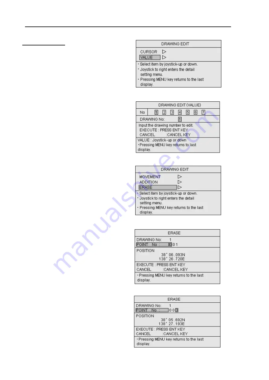
c. Deleting a node


(1)  Press the MENU key to display the menu. 

(2)  Press the Joystick up or down to highlight 

DRAWING EDIT.   

(3)  Press the joystick to the right to enter the 

DRAWING EDIT menu. (Figure 6.56) 

(4)  Highlight VALUE pressing the Joystick up or 

down. 


(5)  Press the Joystick to the right to enter the 

DRAWING EDIT (VALUE) menu. (Figure 

6.57) 

(6) Enter the drawing number using the 

alphanumeric keys or moving the Joystick 

up or down.   

(7)  Press the ENT key to fix the entry. 


(8)  Press the Joystick up or down to highlight 

ERASE. (Figure 6.58) 


(9)  Press the Joystick to the right to enter the 

ERASE menu.   

(10) Enter the node number (POINT No in the 


menu) using the alphanumeric keys. 

 (Figure 

6.59, 

6.60) 


(11) Press the ENT key to fix the entry. 

(12) Press the MENU key 5 times to return to the 

 normal 

display. 

Figure 6.56 DRAWING EDIT menu 

Figure 6.58 DRAWING EDIT menu 

Figure 6.59 ERASE menu (1)   

Figure 6.60 ERASE menu (2)   

Figure 6.57 DRAWING EDIT (LIST) menu 

Summary of Contents for GTD-110

Page 1: ......

Page 2: ......

Page 3: ......

Page 4: ...applied in the document only the document number of the relevant sheet s and cover sheet are modified and the rest of the sheets are not changed The document number is shown in the footer area right o...

Page 5: ...trostatic build up from carpet clothes seats etc z Display Front Plate A glass plate is used in front of the Liquid Crystal Display in the GTD 110 display unit The glass is vulnerable against mechanic...

Page 6: ...arning High Voltage mark Prohibition mark To handle the equipment ignoring this sign may lead to injury to the human body or damage to the equipment Alarm To handle the equipment ignoring this sign ma...

Page 7: ...contents as well as refer to detailed information for your specific requirement Chapter 1 General Information About GPS Outline of the equipment Applicable standards Equipment composition Software ty...

Page 8: ...g up for Waypoint Navigation Marking the POB Person Over Board location Changing the screen top direction Object information Chapter 6 Using the Menu Menu functions Mark block number Setting the alarm...

Page 9: ...5 Chapter 9 Maintenance Periodic inspection and cleaning Chapter 10 Technical References Details of input serial data Details of output serial data Data input output serial line Connector pinouts Ann...

Page 10: ...ter 1 General Information Contents Page No 1 1 About GPS 1 1 1 1 1 General 1 1 1 1 2 Positioning by GPS 1 1 1 1 3 Time required for position fix 1 1 1 2 Outline of the equipment 1 2 1 3 Applicable sta...

Page 11: ...your position latitude longitude and height is determined at the intersection point of four spheres formed by four satellites 1 1 3 Time required for position fix In the following circumstances your...

Page 12: ...es according to the type i e 10 4 inch Diagonal for GTD 110 and 15 inch for GTD 150 The panning and scrolling speed is greatly improved by using the latest digital technology The operation is simple a...

Page 13: ...ries Marine Radar MD 3420 3441 MD 3641 3642 MD 3840 MD 3010 3020 3050 3210 series Marine Radar with ATA MDC 721 741 740 MDC 1541 1540 1560 1510 1520 MDC 1021 1041 1040 MDL 1121 1141 1140 Marine Radar...

Page 14: ...GTD 110 150 Chapter 2 Equipment Composition 93151542 01 Contents Chapter 2 Equipment Composition Contents Page No 2 1 Standard Equipment list 2 1 2 2 Option items list 2 1...

Page 15: ...3 5M 6 pin waterproof connectors LTW both ends 5 m 7 Connecting cable CW 374 5M 6 pin connector 6 pin waterproof connector LTW 5 m 8 Connecting cable CW 375 5M 6 pin waterproof connector Conxal 6 pin...

Page 16: ...3 Specification 93151542 00 Contents Chapter 3 Specification Contents Page No 3 1 Specification 3 1 3 2 Serial data 3 1 3 3 Power requirements 3 2 3 4 Environmental conditions 3 2 3 5 External dimens...

Page 17: ...OP Navigation data display Own ship s position Own ship s course Own ship s speed Waypoint position Waypoint bearing Waypoint distance POB position POB bearing POB distance Cursor position Cursor bear...

Page 18: ...rage temperature 70o C Humidity 93 3 at 40o C 2 Vibration The equipment operates normally under the following vibrating conditions 2 5 Hz 13 2 Hz Amplitude 1mm 10 Maximum acceleration of 7 m s2 at 13...

Page 19: ...GTD 110 150 Chapter 3 Specification 93151542 00 3 3 Unit mm Figure 3 1 The Exterior of GTD 110 with dimensions Figure 3 2 Service space required for GTD 110 Unit in mm inch...

Page 20: ...Chapter 3 GTD 110 150 Specification 3 4 93151542 00 Unit in mm inch Figure 3 3 The Exterior of GTD 150 with dimensions Figure 3 4 Service space required for GTD 110...

Page 21: ...ation 4 1 4 2 Unpacking of the goods 4 1 4 3 Inspection of the goods 4 1 4 4 Siting the units 4 1 4 5 Cable routing and connections 4 1 4 6 Display Installation 4 2 4 6 1 Table mounting 4 2 4 6 2 Flus...

Page 22: ...all of the items stated in the packing list are contained in the package If not report this to an insurance agent for tracing missing goods or a refund 4 3 Inspection of goods Carefully check the ext...

Page 23: ...t with four 4 tapping screws 4 Reset the display unit on to the bracket and fix it using the two screws that were removed in step 1 Refer to the following figures for detail GTD 110 150 The EMI noise...

Page 24: ...ounting mode Display Unit Mounting bracket Fixing screws M5 screw 6 pcs Washer 60 2 23 64 240 9 29 64 37 1 29 64 47 1 27 32 Knurled fixing bolt Unit in mm inch Unit in mm inch Unit in mm inch 60 2 23...

Page 25: ...5 screw 5 pcs Mounting bracket Washer Knurled fixing bolt Figure 4 4 Fitting detail of GTD 150 in table mounting mode 147 5 25 32 65 2 9 16 Display unit Unit in mm inch Figure 4 5 Service space requir...

Page 26: ...fix the display select an appropriate screw length that best suits fixing the unit to the panel thickness 5 Refit the coverings removed in step 3 Figure 4 6 Fitting GTD 110 in flush mounting mode Open...

Page 27: ...Fixing screws M4 screws 4 pcs Screw covers 4 pcs Before installing the unit remove the washer and knurled fixing bolt attached on both sides of the display Figure 4 9 Dimensions of opening and fixing...

Page 28: ...C 1541 1540 1560 1510 1520 MDC 1021 1041 1040 MDL 1121 1141 1140 Marine Radar with ATA MD 3641 3642 3840 Color Fish Finder CVS 108 118 CVS 832 CVS 8841 8842 8816 CVS 8851 8852 CVS 8826 8826S Color Fis...

Page 29: ...ack display has a waterproof design meeting the requirements of IPX 5 Resistive against driven water In order to maintain this specification all the connectors used in an existing external sensor must...

Page 30: ...5 3 Getting started 5 6 5 3 1 Turning the power on 5 6 5 3 2 Turning the power off 5 7 5 3 3 Changing the display and panel brightness 5 7 5 4 Displaying the current position 5 7 5 5 Operation on the...

Page 31: ...ting a waypoint by the mark number 5 15 5 7 4 Resetting a point of origin for the waypoint navigation 5 16 5 7 5 Canceling the waypoint navigation 5 16 5 8 Marking the POB Person Over Board location 5...

Page 32: ...GTD 110 150 Chapter 5 Basic Operation 93151542 00 Contents 5 14 Measuring the bearing and distance between two points 5 23...

Page 33: ...ess of the key displays the brightness scale bar graph A further press of the key changes the brightness and illumination first increasing and then decreasing 5 1 2 Marking control and keys This funct...

Page 34: ...nd edit the ship s track Functional details of controls and key switches involved in this function are as follows TRACK color control Selects the color of a track Colors are expressed alphabetically a...

Page 35: ...map is continuously enlarged HOME key Puts own ship s position or cursor position in the center of the screen Zoom in key Contracts the map scale when pressed When it is pressed and held the map is co...

Page 36: ...he menu screen ENT key Enters a preset menu item CANCEL key Cancels an entered menu item CLR key Cancels the anchor watch or waypoint designation 5 1 7 Screen control keys CUR key Turns the cross curs...

Page 37: ...hniques providing chart data on the screen Dynamic Nav Aids an innovative and dynamic presentation mode Dynamic Elevation Data optimized palettes for chart plotter with more than 256 colors includes n...

Page 38: ...unit is turned on The battery status display is shown at first When the battery is near the end of its life the display Replacement needed is shown and an audio alarm will be activated In such a case...

Page 39: ...f Position coordinate The LOP coordinate display is available for Loran C Select DISPLAY SETTINGS and then POSITION DATA DISPLAY to display own ship s position For detail refer to Para 6 4 1 Position...

Page 40: ...play with own ship s mark being centered on the screen 5 5 2 1 Shifting the map display There are two shift modes available VIEW POINT and CHART Select SYSTEM SETTINGS 1 2 SCRL DIRECTION and then sele...

Page 41: ...position whether it is within or outside the screen Pressing the HOME key resets the map display with own ship s mark to be centered on the screen Press the CUR key to turn the cross cursor off Own sh...

Page 42: ...ore the ship s track The number of ship s track plots is shown in the lower right corner of the screen NOTE Frequent pressing of the ROUTE key toggles the ship s track line display between ON and OFF...

Page 43: ...o Para 5 4 8 and Para 5 4 9 for the procedure 5 5 6 Recalling ship s track 1 Press the RCL key 2 Operate the Joystick up or down to select the block number to be recalled 3 If an unwanted ship s track...

Page 44: ...6 Mark registration The GTD 110 150 can register up to 8 300 points with registration numbers assigned from 0 to 8 299 Each point can be assigned with different marks and colors Registering points wit...

Page 45: ...by color and shape 1 Delete the cross cursor display by pressing the CUR key 2 Press the MARK ERASE key The MARK ERASE pop up window will appear 3 Operate the Joystick in the window to point to the co...

Page 46: ...t on the route as a waypoint Use the following procedure to set a waypoint 1 Delete the cross cursor by pressing the CUR key The following example shows that mark number 53 is set as a waypoint 2 Pres...

Page 47: ...nd press the GOTO key The marked point is set as a waypoint 5 7 3 Resetting a waypoint by a mark number 1 Press the GOTO key The Waypoint setting pop up window will appear with prompt 2 Operate the Jo...

Page 48: ...Press the ENT key The ship s current position is reset as a new point of origin for the current waypoint navigation 5 7 5 Canceling waypoint navigation 1 Press the GOTO key The Waypoint setting windo...

Page 49: ...oint press the POB key and then press the ENT key A new POB point will be set with a POB mark and its latitude and longitude are shown on the screen 5 8 2 Canceling the POB 1 Press the POB key 2 Press...

Page 50: ...ou need to input the VTG sentence in NMEA 0183 sent from an external navigation receiver As long as the KODEN GPS sensor KBG 2 KBG 3 GPS 10A is connected you do not need to worry about this setting Th...

Page 51: ...is shown in the OBJECT INFORMATION window To display the object information 1 Press the INFO key The OBJECT INFORMATION window will appear showing the object item 2 Move the joystick to highlight the...

Page 52: ...the draught By operating the joystick this cursor can be moved up and down and the draught can be displayed on a particular graph point 2 The vertical red line in the graph is the cursor to read the...

Page 53: ...The color and the shape of the mark are the same as the mark input of the last key operated before the external event switch was turned on TLL The shape of the mark is and the color is red 5 13 2 The...

Page 54: ...in the MENU setting The two methods are MANUAL and TIME OUT For MANUAL when the CLR key is pressed active is changed to fixed For TIME OUT five seconds after the event input or reference operation has...

Page 55: ...he first point and press the ENT key A pop up window labeled POINT TO POINT will appear at the top right corner of the screen Figure 6 15 3 Move the cross cursor on to the second point and press the E...

Page 56: ...DISPLAY SETTINGS 6 5 6 4 1 POSITION DATA DISPLAY 6 5 6 4 2 CHART DISPLAY 6 6 6 4 3 MARINE DISPLAY 6 7 6 4 4 LAND DISPLAY 6 8 6 4 5 DEPTH DISPLAY 6 8 6 4 6 SCREEN DISPLAY SETTING 6 9 6 4 6 1 COURSE LIN...

Page 57: ...CORRECTION 6 21 6 6 12 NAVIGATION MODE 6 21 6 6 13 OUTPUT SETTING 6 22 6 6 14 EVENT TEMPORARY STORE 6 22 6 6 15 EVENT DISPLAY CHANGE 6 22 6 7 MARK EDIT 6 24 6 7 1 EDIT 6 24 6 7 2 TRANSFER 6 24 6 7 3 D...

Page 58: ...ding a node 6 35 c Deleting a node 6 36 6 11 TRACK COLOR SETTING 6 37 6 12 6 OTHER SHIPS PLOTTING SETTINGS 6 38 6 13 User C Card 6 40 6 13 1 STORE 6 40 6 13 2 RECALL 6 42 6 13 3 ERASE 6 44 6 13 4 FORM...

Page 59: ...of POS WPT POB INFORMATION WINDOW SETTING NO L L TIME W_TEMP TIME TTG TIME ETA LORAN C DISPLAY SETTINGS CURSOR WINDOW SETTING NO L L LORAN C GPS DGPS SETTINGS To set up GPS DGPS for proper operation...

Page 60: ...S Setting other ship s data STORE To save the data into the User C Card RECALL To recall the data from the User C Card ERASE To cancel the data stored in the User C Card USER C CARD FORMAT To format t...

Page 61: ...the right The ALARM SETTINGS set up menu will appear Confirm ARRIVAL ALARM YES is highlighted If NO is highlighted press the Joystick to the left to highlight YES 3 Press the Joystick downward to sel...

Page 62: ...ved by regularly scanning the map data forward of own ship s position The execution interval of the scanning is 2 seconds The Figure below shows the range of scanning Detected dangerous items are as f...

Page 63: ...er each sub menu 1 POSITION DATA DISPLAY 5 DEPTH DISPLAY 2 CHART DISPLAY 6 SCREEN DISPLAY SETTING 3 MARINE DISPLAY 7 INFORMATION WINDOW SETTING 4 LAND DISPLAY 8 CURSOR WINDOW SETTING 6 4 1 POSITION DA...

Page 64: ...Superimposes and displays where the reduced scale level is different on the map OFF Bound Lines The range of the map data is shown with the frame OFF Grid Displays the latitude longitude line In the...

Page 65: ...ip s position Black light The light of the lighthouse is not visible from the point of observation Grey light The light of the lighthouse is off Red Green Yellow light Color of the lighthouse OFF Land...

Page 66: ...an item in the sub menu Table 6 5 LAND DISPLAY menu items Items Detail Initial Setting Soundings Selects the setting for the display of soundings ON OFF OFF Sounding Range Min Sets the minimum value...

Page 67: ...s are available LINE A line is drawn from own ship to the edge of the screen SPD RESP The line length changes according to own ship s speed NO No Course Line is shown Initial setting LINE 6 4 6 2 COUR...

Page 68: ...e thickness of a ship s track Selections THICK LINE and THIN LINE Initial setting THICK LINE 6 4 6 5 MARK SIZE Selects the size of a mark Selections LARGE and SMALL Initial setting LARGE 6 4 6 6 CURSO...

Page 69: ...erenced to own ship as a distance marker The scale bar shown at the left bottom of the screen indicates the interval of each ring Selections NO and YES Initial setting NO In the Perspective View mode...

Page 70: ...ers is turned off by the user Depth Attention Areas Track Routes Lighthouse Buoys Signals Light animation Underwater Objects Depth Range Min setting is more than 20m or Depth Range Max setting is less...

Page 71: ...e registration mark color and the direction another ship exists in can be confirmed in real time The direction of the other ship is seen from the own ship s position Current Direction Calculates from...

Page 72: ...the route number the waypoint number and Time Required Estimated Time of Arrival Displays the route number the waypoint number and estimated time of arrival TTG ETA Displays Time Required and the esti...

Page 73: ...apsed time of POB Displays the elapsed time after POB was set Setting time of POB Displays the time when POB was set Menu operation Make the setting of Added Info of POB ON by operating the joystick t...

Page 74: ...r The following setting items are available for GPS DGPS sensor Table 6 9 GPS DGPS setting items Items to be set Selections Description DATUM WGS 84 DATUM is fixation with WGS 84 AVERAGE 1 2 3 Initial...

Page 75: ...S DGPS signal reception is interrupted or the sensor is out of function select YES and press the ENT key If the failure still persists contact KODEN or your nearest service agent for repair 6 6 SYSTEM...

Page 76: ...me 1 second 600 seconds Distance 0 01nm 10 0nm Initial setting 10 seconds 6 6 3 NUMBER OF PLOTS This function is used to set up the upper limit of plotting numbers Plots are erased on a first in first...

Page 77: ...6 7 SCRL DIRECTION Sets up the screen scroll direction Selection VIEW POINT The chart moves towards the direction to which the Joystick is pressed Own ship moves opposite to the chart CHART The chart...

Page 78: ...e time when the Mark and Route are registered z The current time display in the Information window Selection 13 5 13 5 hours Initial setting 0 0 hours Use the following procedures to set up the local...

Page 79: ...sation shall be set in a range of 90 0 to 90 0 The amount of compensation can be set in a unit of 0 1 each by pressing the Joystick To the right 0 1 each increase to the left 0 1 each decrease 6 6 12...

Page 80: ...TEMPORARY STORE Use the event temporary store function by putting events into memory using mark numbers 0 to 99 The EVENT TEMPORARY STORE functions by setting MARK BLOCK NUMBER to 00000 and selecting...

Page 81: ...ied out You can switch the method of changing the color of the frame of the window by this setting When TIME OUT is selected the color of the frame of the window automatically changes to black five se...

Page 82: ...ing of mark shape mark color comments and latitude longitude of the marked point Move the Joystick right or left to select an item and up and down for selecting a value or mark shape 6 7 2 TRANSFER Tr...

Page 83: ...as of interest for various purposes Figure 6 27 6 8 2 TRANSFER OF BLOCKS Transfers the data of a certain block number to another block number Original block number data will be deleted after this oper...

Page 84: ...Displays the measured data CH1 CH4 Displays the numbers and reception S N of 4 satellites from a large elevation angle The S N index of 5 or larger indicates the GPS signal reception is in good order...

Page 85: ...d is used when each node of the area can be read from a chart such as a fishery zone a dangerous zone etc To draw 1 In the DRAWING menu select a DRAWING BLOCK from 1 to 7 2 Select the LINE THICKNESS e...

Page 86: ...ix Repeat this procedure for other nodes If you enter a node position by mistake press the CANCEL key Each time this key is pressed the entered block number returns to the previous number 8 To finish...

Page 87: ...ng 6 Press the ENT key 7 Press the MENU key to exit 6 10 3 DRAWING RECALL All the drawing displays can be recalled or cancelled one by one Use the following procedure to perform this function 1 In the...

Page 88: ...AWING EDIT menu Figure 6 36 4 Press the Joystick up or down to highlight CURSOR and then press it to the right The DRAWING EDIT sub menu will appear Figure 6 37 5 Highlight MOVEMENT and press the Joys...

Page 89: ...0 4 Press the Joystick up or down to highlight ADDITION 5 Press the Joystick to the right to enter the ADDITION menu Figure 6 41 6 Move the Joystick to place the cross cursor on a node of a graphic dr...

Page 90: ...ENT key to fix the position of the node Figure 6 42b 10 To return to the normal display press the MENU key 4 times Figure 6 42a ADDITION menu 2 1 Press the MENU key to display the menu 2 Press the Jo...

Page 91: ...ck to the right to display the DRAWING EDIT menu Figure 6 46 3 Press the Joystick up or down to highlight VALUE 4 Press the Joystick to the right to enter the DRAWING EDIT LIST menu Figure 6 47 5 Ente...

Page 92: ...OINT No Figure 6 50 11 Move the Joystick up or down to highlight POSITION Figure 6 51a 12 Press the Joystick to the right to highlight the first digit of the latitude value Figure 6 51b 13 Enter the l...

Page 93: ...g the Joystick up or down Figure 6 53 6 Press the ENT key to fix the entry 7 Press the Joystick up or down to highlight ADDITION in the DRAWING EDIT VALUE menu Figure 6 54 8 Press the Joystick to the...

Page 94: ...6 Enter the drawing number using the alphanumeric keys or moving the Joystick up or down 7 Press the ENT key to fix the entry 8 Press the Joystick up or down to highlight ERASE Figure 6 58 9 Press th...

Page 95: ...elated to an order of colors green red yellow cobalt blue blue pink white The water temperature s numerical value of each color cannot be set to more than the numerical value of the next color Menu op...

Page 96: ...MIT Selects maximum number of plots 50 100 200 500 1000 CRS LINE Selects type of course line SPD RESP NO See NOTE Operating procedure 1 Press the MENU key to display the Main menu 2 Move the Joystick...

Page 97: ...6 39 An example display of the ship s plot display is shown in Figure 6 65 in which 3 ships are under plot with own ship s track other ship s ID numbers and their SPD RESP course lines being shown Fi...

Page 98: ...PLOT DATA of 10 kinds 0 9 to be stored on a track basis SYSTEM To set the setting environment 6 13 1 STORE 1 Press the MENU key to display the Main menu 2 Press the Joystick up or down to highlight US...

Page 99: ...ame entry is finished press the ENT key to save the data When the data is successfully saved the message Data storage complete will appear 5 To return to the normal Nav display press the MENU key 4 ti...

Page 100: ...6 6 14 3 ERASE for details The data storage has failed Please retry from the first step This message indicates that data saving has failed due to extraction of the User C Card during the data saving o...

Page 101: ...ume the backed up set up environment 1 Move the Joystick up or down to highlight the file to be recalled and press the ENT key The message Do you wish to overwrite SYSTEM will appear 2 If YES press th...

Page 102: ...oystick up or down to highlight USER C CARD and press the Joystick to the right to enter its menu Figure 6 74 3 Move the Joystick up or down to highlight ERASE and press the Joystick to the right to e...

Page 103: ...y data already stored in the User C Card by an unintentionally formatting Formatting time is about 10 seconds Use the following procedure to format 1 Press the MENU key to open the Main menu 2 Move th...

Page 104: ...perate the joystick to the right and display the subscreen of NEAREST PORT INFO 4 In this subscreen the information to be retrieved is displayed as a list of icons Move the highlight to the item that...

Page 105: ...ram for testing electronic components like the LCD Liquid Crystal Display RAM Random Access Memory Key switches the Joystick rotary switches and the buzzer Tests for LCD brilliance and the COM port ar...

Page 106: ...1 4 Resetting a point of origin 7 7 7 1 5 Canceling a route 7 8 7 1 6 Editing a route 7 8 7 1 6 1 Editing a route using the cross cursor 7 8 a Moving a waypoint 7 9 b Adding a waypoint point 7 11 c D...

Page 107: ...n to highlight ROUTING Figure 7 2 5 Press the Joystick to the right to enter the ROUTING sub menu 6 Press the Joystick up or down to highlight CURSOR Figure 7 3 7 Press the Joystick to the right The R...

Page 108: ...d by the waypoints set above 5 The route and waypoints are deleted and again the ROUTING Route Name Registration menu window will appear To register another route perform the procedure described in Pa...

Page 109: ...omatically 2 Press the Joystick down to highlight COMMENT 3 Press the Joystick to the right to enter COMMENT sub menu 4 Enter texts using the alphanumeric keys See NOTE and press the ENT key to fix th...

Page 110: ...2 for further waypoint registrations 7 Press the MENU key to fix the entries b By LOP value 1 Press the Joystick to the left to highlight MARK NUMBER 2 Press the Joystick down to highlight POSITION 3...

Page 111: ...display the ROUTE EXECUTE window Figure 7 11 3 Press the Joystick to allow the cross cursor to fall on the route 4 Press the ROUTE key to select the route The route number and its name date of creatio...

Page 112: ...to highlight the route number Alternatively you can use the alphanumeric keys to enter the route number NOTE To change the course follow up order press the GOTO key Each press of the key changes the o...

Page 113: ...point of origin To do 1 Press the ROUTE key while the GTD 110 150 is in the navigation mode 2 Press the GOTO key to change the waypoint The course line will be re drawn from own ship s position to the...

Page 114: ...registered data will not be deleted even if this operation is performed 7 1 6 Editing a route This function allows you to edit a registered route by moving adding or deleting waypoints on the route 7...

Page 115: ...DIT 5 Press the Joystick to the right to enter the ROUTE EDIT window 6 Press the Joystick up or down to highlight CURSOR Figure 7 21 7 Press the Joystick to the right to show the ROUTE EDIT sub menu w...

Page 116: ...point number lat lon will be shown in the WAYPOINT MOVEMENT window NOTE If some waypoints are overlapped or situated nearby you can choose each waypoint one by one by repeatedly pressing the ROUTE key...

Page 117: ...re 7 25 ROUTE menu Figure 7 26 ROUTE EDIT menu 2 Figure 7 27 ROUTE EDIT menu 1 Figure 7 28 WAYPOINT ADDITION window 1 5 Press the Joystick up or down to highlight WAYPOINT ADDITION Figure 7 27 6 Press...

Page 118: ...al display press the menu key 5 times NOTE 2 If more than 50 waypoint data are entered the following message will be shown to notify that memory is full The registration memory is full To register new...

Page 119: ...ck to move the cross cursor on to the waypoint to be deleted 10 Press the ROUTE key to select the waypoint The waypoint data waypoint number lat lon will be shown in the WAYPOINT DELETE window Figure...

Page 120: ...will appear Figure 7 37 5 Press the Joystick up or down to highlight VALUE and press the Joystick to the right to enter its sub menu The ROUTE EDIT LIST menu will appear Figure 7 38 6 Assign the rout...

Page 121: ...ft to highlight WAYPOINT No 12 Press the Joystick down to highlight POSITION 13 Press the Joystick to the right to highlight the first digit of the latitude Figure 7 41a or Figure 7 41b 14 Use the alp...

Page 122: ...light ROUTE EDIT and press the Joystick to the right The ROUTE EDIT menu will appear Figure 7 43 4 Highlight VALUE and press the Joystick to the right The ROUTE EDIT LIST will appear Figure 7 44 5 Ent...

Page 123: ...o the left to highlight WAYPOINT No 11 Press the Joystick down to highlight POSITION 12 Press the Joystick to the right to highlight the first digit of the latitude 13 Enter the latitude value and the...

Page 124: ...TE menu will appear Figure 7 48 3 Highlight ROUTE EDIT and press the Joystick to the right The ROUTE EDIT menu will appear Figure 7 49 4 Highlight VALUE and press the Joystick to the right The ROUTE E...

Page 125: ...to the right The WAYPOINT DELETE menu will appear Figure 7 52a or Figure 7 52b 9 Enter the waypoint number to be deleted using the alphanumeric keys or the Joystick Figure 7 53 10 To return to normal...

Page 126: ...pear Figure 7 54 3 Press the Joystick up or down to highlight ROUTE EDIT 4 Press the Joystick to the right to show the ROUTE EDIT menu Figure 7 55 5 Highlight VALUE and press the Joystick to the right...

Page 127: ...ight COMMENT EDIT in the ROUTE EDIT sub menu 9 Press the Joystick to the right to enter the COMMENT EDIT menu Figure 7 58 10 Enter the comment using the alphanumeric keys 11 Press the ENT key to fix t...

Page 128: ...0 4 Press the Joystick up or down to highlight CURSOR 5 Press the Joystick to the right to display the ROUTE ERASE sub menu Figure 7 61 6 Move the cross cursor to any point on the route to be deleted...

Page 129: ...ess the Joystick to the right to enter the ROUTE ERASE menu Figure 7 64 4 Highlight LIST and press the Joystick to the right The ROUTE ERASE sub menu will appear Figure 7 65 5 Enter the route number t...

Page 130: ...the ENT key while the MARK STORE menu is shown This menu will disappear in 5 seconds Figure 7 66 3 Enter texts using the Alphanumeric keys Figure 7 67 NOTE If you press the CANCEL key at this stage al...

Page 131: ...play the menu 2 Highlight MARK EDIT and press the Joystick to the right The MARK EDIT L L menu will appear Figure 7 68 3 Press the Joystick up or down to highlight EDIT 4 Press the Joystick to the rig...

Page 132: ...ht COMMENT Figure 7 71a 8 Press the Joystick to the right to enter the comment area 9 Press the alphanumeric keys to enter texts for comment Figure 7 71b 10 Press the ENT key to fix the entry 11 To re...

Page 133: ...isplayed even if the POWER switch is pressed 8 1 8 2 2 Own ship s position is not shown in the screen 8 1 8 2 3 Own ship s mark does not blink and no position fix available 8 1 8 2 4 Own ship s positi...

Page 134: ...on If the failure persists contact your local KODEN dealer Q Does the main supply voltage lie between 10 8 31 2 VDC A If the answer is NO check the following points 1 Check if the MAIN switch at the...

Page 135: ...tion by selecting AVERAGE SPEED NO in the SYSTEM SETTING 2 If the speed averaging is still necessary select an appropriate index AVERAGE NUMBER A2 Check if the GPS DGPS averaging constant is set to 3...

Page 136: ...GTD 110 150 Chapter 9 Maintenance 93151542 00 Contents Chapter 9 Maintenance Contents Page No 9 1 Periodic inspection and cleaning 9 1 9 1 1 Monthly check 9 1...

Page 137: ...connections and cables 9 1 1 Monthly check If the display screen is dirty clean the screen with a soft cloth damped with anti static agent or pure water Do not use a dry cloth as it causes static bui...

Page 138: ...a specification 10 1 10 1 3 Details of input sentences 10 1 10 2 Details of output serial data sentence 10 5 10 2 1 Output data format 10 5 10 2 2 Output data specification 10 5 10 2 3 Details of outp...

Page 139: ...bit provided Data Bit ASCII Code Logic 0 4V Logic 1 0 5V Start Bit D0 D1 D2 D3 D4 D5 D6 D7 Stop Bit Parity bit none _ _GGA hhmmss XXXX XXX N S XXXXX XXX E W Start of sentence Talker device Sentence n...

Page 140: ...l strength SS dB 1 V m SD MTW XX C hh CR LF Temperature degree C Checksum Start of sentence Talker device Sentence name _ _ GLL XXXX XXX N S XXXX XXX E W hh CR LF Sentence name Start of sentence Talke...

Page 141: ...X a X X X X a c c a a hhmmss ss a hh CR LF Target distance from own ship Target status see NOTE 1 NOTE 1 L Lost Tracked target has been lost Q Query target in the process of acquisition T Tracking Tim...

Page 142: ...X XX XX XX XX XX XX XX XX CR LF Quality indicator 1 GPS positioning 0 Positioning unable Averaging constant Satellite elevation angle Satellite number Satellite azimuth angle Elevation angle limit N S...

Page 143: ...I code Logic 0 4V or more Logic 1 0 5V or more Start bit D0 D1 D2 D3 D4 D5 D6 D7 Stop bit Parity bit none Checksum XXX X X hh CR LF GP APB X X XX X X N X X XXX X X XXX XX XXX X X XTE units nautical mi...

Page 144: ...West N North S South Start of sentence Talker device Sentence name GP GGA hhmmss XXXX XXX N S XXXXX XXX E W X XX XXX 0 XXXX M 0 XXX M hh CR LF UTC of position Latitude Longitude N S Latitude N S Chec...

Page 145: ...te Ver 2 0 GP ZDA hhmmss XX XX XX hh CR LF Course degrees true Checksum Speed knots Start of sentence Talker device Sentence name Speed km h GP XTE X X XX X X N hh CR LF Fixed to A Data valid Units na...

Page 146: ...put impedance 470 Device Opto coupler Type TLP181 G8 Toshiba 10 3 2 Serial data output Connector name NMEA GPS SENSOR The connector used Type LTWD 06BFFA L180 Output current 20mA max Device RS232C Dri...

Page 147: ...outs J1 J2 J4 J5 1 GND 2 TX Output 3 GND Output 4 RX Input 5 RX Input 6 NC 1 GND Output 2 GPS OUT Output 3 GND Output 4 GPS IN Input 5 GPS IN Input 6 12V Output POWER 1 DC Input 2 DC Input 3 NC 4 NC 5...

Page 148: ...GTD 110 150 Annex 93151542 00 Annex Annex Contents Page No A 1 GTD 110 150 Menu tree A 1 A 2 Color palette list for GTD 110 150 A 6...

Page 149: ...GROUNDING ALARM REPORT DISPLAY POSITION DATA DISPLAY L L LORAN C SETTINGS CHART Map Color Normal SunLight NightVision NOAA DISPLAY Mixing Levels ON OFF Bound Lines ON OFF Grid ON OFF Value Added Data...

Page 150: ...ICK LINE THIN LINE MARK SIZE LARGE SMALL CURSOR TYPE STANDARD LONG LINE BG OF POSINFO OFF ON RING MARKER OFF ON SAFETY STATUS BAR OFF ON QUICK INFO OFF ON Added info of POS OFF ON Added info Hidden Cl...

Page 151: ...SCRL DIRECTION VIEW POINT CHART EST POSITION AUTO OWN SHIP POSITION CORRECTION YES NO LOCAL TIME CORRECTION 13 5 13 5 hour COMPASS CORRECTION 90 o 90 o NAVIGATION MODE GREAT CIRCUIT RHUMB LINE OUTPUT...

Page 152: ...THICK INOUT METHOD CURSOR VALUE DRAWING ERASE DRAWING No 1 7 DRAWING RECALL BLOCK No 1 7 DRAWING EDIT CURSOR MOVEMENT DRAWING No 1 7 ADDITION DRAWING No 1 7 ERASE DRAWING No 1 7 VALUE MOVEMENT DRAWIN...

Page 153: ...OYSTICK TEST ROTARY SW TEST BRILLIANCE TEST COM PORT TEST BUZZER TEST COLOR PALETTE COLOR PALETTE NUMBER 001 254 PALETTE OPERATION RED 000 255 GRN 000 255 BLU 000 255 DATA OUTPUT MARK COMMUNI TRACK CU...

Page 154: ......

Reviews: