Chapter 4. Display
4-1
Chapter 4. Display
Introduction
The Display (
Disp
) Menu is used to set up
the parameters that govern the display
functions when vessel monitoring. This
chapter covers the functions in the
Disp
Menu. Explanations of each of the functions
are provided. Additionally, detailed navigation
procedures through the menu tree are
provided for a few of the functions to help the
user become familiar with the use of the
keyboard functions described in
Chapter 3, Menu Tree, Keyboard Functions,
and Quick Start.
Unless otherwise noted, the display function
for each channel (such as units, ID, etc.) can
be set differently. The descriptions below for
each function note those that are global in
nature and that affect the display for all
channels.
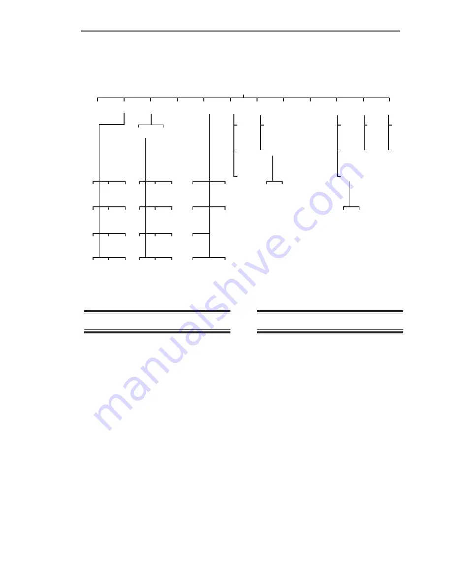
As shown in Figure 4-1, the
Disp
Menu has
twelve submenus.
Avg
This menu is used to set the number of
individual readings (from 1 to 255) the
Weigh II averages for each display reading
while vessel monitoring. The Weigh II calcu-
lates a running average. The larger the
number of individual readings in the running
average, the smaller effect a variation in
signal will have on the average. This results in
fewer variations on the display reading and an
easier to read display.
Avg
affects the value
seen on the display as well as setpoints,
current outputs, and serial outputs. The
default value for
Avg
is 1.
The number shown upon entry into this menu
is the channel’s current averaging factor. This
number can be modified by using the Up and
Down Arrow Keys or by direct entry with the
Alphanumeric Keys. When the desired
number is shown, pressing the Enter Key
saves the new value.
2
20
200
5k
5
50
500
10k
Figure 4-1. The Display Menu Tree
Disp
Avg Cntby Units ID Form ScanT BarS Cont Brite Time Zclmp Hide
tns
Brl
in
mA
Kgs
Ltr
ft
mV
lbs
gal
%
V
1
10
100
1k
Common Custom
On
Off
Hi
Lo
Set
View
Enab
Span
Enab
1 sec
2 sec
5 sec
XXXX.X
XX.XXX
XXXXX0
XXXXX
XXX.XX
X.XXXX
XXXXX00
Off
On
No
Yes
Summary of Contents for Weigh II
Page 12: ...2 4 Chapter 2 Hardware Installation...
Page 20: ...3 8 Chapter 3 Menu Tree Keyboard Functions and Quick Start...
Page 50: ...6 12 Chapter 6 Calibration...
Page 68: ...A 2 Appendix A Product Specifications...
Page 70: ...B 2 Appendix B Summary of Commands Used When Vessel Mounting Hot Keys...
Page 77: ...Appendix E E 1 This appendix not used at this time...
Page 78: ...Appendix E E 2...
Page 80: ...Appendix F Technical Drawings F 2...
Page 81: ...Appendix F Technical Drawings F 3...
Page 82: ...Appendix F Technical Drawings F 4...
Page 83: ...Appendix F Technical Drawings F 5...
Page 84: ...Appendix F Technical Drawings F 6...
Page 85: ...Appendix F Technical Drawings F 7...
Page 86: ...Appendix F Technical Drawings F 8...
Page 87: ...Appendix F Technical Drawings F 9...
Page 88: ...Appendix F Technical Drawings F 10...
Page 89: ...Appendix F Technical Drawings F 11...
Page 90: ...Appendix F Technical Drawings F 12...
Page 91: ...Appendix F Technical Drawings F 13...
Page 92: ...Appendix F Technical Drawings F 14...
Page 93: ...Appendix F Technical Drawings F 15...
Page 94: ...Appendix F Technical Drawings F 16...
Page 95: ...Appendix F Technical Drawings F 17...
Page 96: ...Appendix F Technical Drawings F 18...
Page 97: ...Appendix F Technical Drawings F 19...
Page 98: ...Appendix F Technical Drawings F 20...
Page 99: ...Appendix F Technical Drawings F 21...
Page 100: ...Appendix F Technical Drawings F 22...
Page 101: ...Appendix F Technical Drawings F 23...
Page 102: ...Appendix F Technical Drawings F 24...
Page 103: ...Appendix F Technical Drawings F 25...
Page 104: ...Appendix F Technical Drawings F 26...
Page 105: ...Appendix F Technical Drawings F 27...
Page 106: ...Appendix F Technical Drawings F 28...
Page 107: ...Appendix F Technical Drawings F 29...
Page 108: ...Appendix F Technical Drawings F 30...
Page 109: ...Appendix F Technical Drawings F 31...
Page 110: ...Appendix F Technical Drawings F 32...
Page 116: ...Appendix G Calculation of Maunal Calibration Parameters G 6...


