3-4
Chapter 3. Menu, Tree, Keyboard Functions, and Quick Start
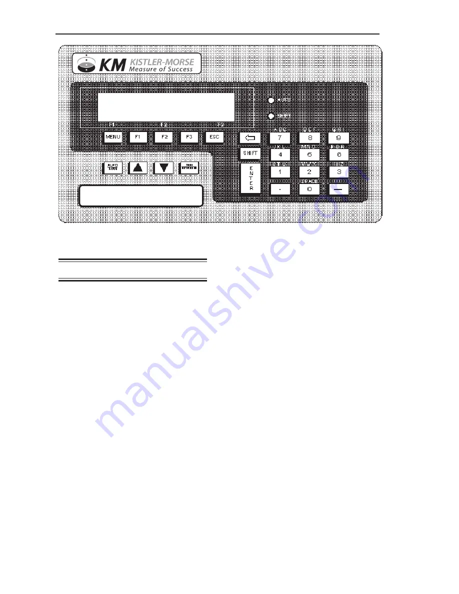
Figure 3-2. Weigh II Faceplate and Display
Display and Keyboard
The Weigh II (Figure 3-2) has a liquid crystal
display (LCD) panel made up of two
16-character lines, and an integral, weather-
sealed membrane keyboard. The LCD
displays the vessel ID, material weight
numerically or in a bar graph format, menu
selections, and error messages.
The Weigh II keyboard is used to access the
different menus, scroll through the vessel
monitoring display screens, input setup and
calibration parameters, label the vessel for
easy identification, etc. The function of each
key on the keyboard is described below.
Auto/Man Key
When vessel monitoring, the Weigh II dis-
plays the factory-set ID number (or the
customer-defined ID, if input) and material
weight. The Weigh II display can be set up to
scroll automatically through the display
screens for each vessel (Auto Mode) or
remain fixed on a selected vessel (Manual
Mode). The Auto/Man Key toggles between
Auto and Manual Modes:
• When the Weigh II is in the Auto Mode,
the display remains on one vessel for a
preset period of time before scrolling to the
next vessel. The preset display time can
be changed to suit the operator needs,
using the
ScanT
function (see ScanT in
Chapter 4, Display). The Auto LED to the
right of the LCD is illuminated when the
Weigh II is in the Auto Mode.
• When the Weigh II is in the Manual Mode,
the display remains fixed on a selected
vessel and must be scrolled manually with
the Up Arrow and Down Arrow Keys to
display information on another vessel. The
Auto LED is off when the Weigh II is in the
Manual Mode.
The Auto/Man Key is also used to exit
any function in the menu tree and return
the display to vessel monitoring in the
Manual Mode.
Up Arrow and
Down Arrow Keys
The Up Arrow and Down Arrow Keys are used
to manually scroll the display through the
vessels when the Weigh II is vessel monitor-
ing in the Manual Mode.
These keys are also used to scroll to desired
values when in the menu tree, entering setup
and calibration parameters. For example,
when setting the
Lo Span
and
Hi Span
values
in the
Auto Cal
Menu, the Up Arrow and
Down Arrow Keys can be used to scroll to a
desired value.
WEIGH II
Summary of Contents for Weigh II
Page 12: ...2 4 Chapter 2 Hardware Installation...
Page 20: ...3 8 Chapter 3 Menu Tree Keyboard Functions and Quick Start...
Page 50: ...6 12 Chapter 6 Calibration...
Page 68: ...A 2 Appendix A Product Specifications...
Page 70: ...B 2 Appendix B Summary of Commands Used When Vessel Mounting Hot Keys...
Page 77: ...Appendix E E 1 This appendix not used at this time...
Page 78: ...Appendix E E 2...
Page 80: ...Appendix F Technical Drawings F 2...
Page 81: ...Appendix F Technical Drawings F 3...
Page 82: ...Appendix F Technical Drawings F 4...
Page 83: ...Appendix F Technical Drawings F 5...
Page 84: ...Appendix F Technical Drawings F 6...
Page 85: ...Appendix F Technical Drawings F 7...
Page 86: ...Appendix F Technical Drawings F 8...
Page 87: ...Appendix F Technical Drawings F 9...
Page 88: ...Appendix F Technical Drawings F 10...
Page 89: ...Appendix F Technical Drawings F 11...
Page 90: ...Appendix F Technical Drawings F 12...
Page 91: ...Appendix F Technical Drawings F 13...
Page 92: ...Appendix F Technical Drawings F 14...
Page 93: ...Appendix F Technical Drawings F 15...
Page 94: ...Appendix F Technical Drawings F 16...
Page 95: ...Appendix F Technical Drawings F 17...
Page 96: ...Appendix F Technical Drawings F 18...
Page 97: ...Appendix F Technical Drawings F 19...
Page 98: ...Appendix F Technical Drawings F 20...
Page 99: ...Appendix F Technical Drawings F 21...
Page 100: ...Appendix F Technical Drawings F 22...
Page 101: ...Appendix F Technical Drawings F 23...
Page 102: ...Appendix F Technical Drawings F 24...
Page 103: ...Appendix F Technical Drawings F 25...
Page 104: ...Appendix F Technical Drawings F 26...
Page 105: ...Appendix F Technical Drawings F 27...
Page 106: ...Appendix F Technical Drawings F 28...
Page 107: ...Appendix F Technical Drawings F 29...
Page 108: ...Appendix F Technical Drawings F 30...
Page 109: ...Appendix F Technical Drawings F 31...
Page 110: ...Appendix F Technical Drawings F 32...
Page 116: ...Appendix G Calculation of Maunal Calibration Parameters G 6...


