


KINOVA
®
Gen3 Ultra lightweight robot
User Guide
21
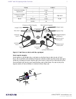
3.
Use appropriate screws to mount either the base controller or the mounting plate to the
surface. If the base controller is mounted directly, the screws will need to go through the
mounting surface from the other side.
Controller mounting plate bolting pattern
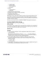
This section describes the bolting pattern of the mounting plate. This is useful when
mounting the robot to a surface using the mounting plate.
Overview
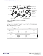
The mounting plate is attached to the bottom of the base controller. The mounting plate has
two sets of M8 screw holes (4) and one set of counter-sunk M6 screw holes (4) available for
mounting the plate to a surface.
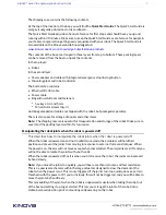
Mounting details
Base controller underside bolting pattern
This section describes the bolting pattern on the underside of the base controller. This is
useful when you want to affix the robot base directly to a surface.
Overview
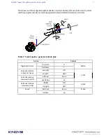
The underside of the controller has four M6 screw holes for mounting purposes. These holes are
used for attaching the mounting plate to the controller. When the mounting plate is removed,
these holes can be used for mounting the controller directly to a surface. In that case, holes
must be drilled through the surface so that screws can go through from the other side and into
the controller mounting holes from underneath.
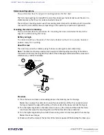
One of the screw holes in the controller base features an inset locking screw. Turning the
locking screw clockwise to the end of its travel (using a 3 mm hex key) while the base shell is
clamped to the controller will lock the two together and prevent the clamp from being opened.
Figure 2: Mounting plate bolting pattern


