


Digital in- and outputs
© KEB, 2008-02
COMBIVERT R6-S
Seite 3.4 - 13
3
10
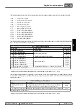
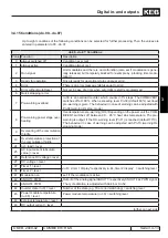
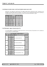
3.4.15 Conditions (do.00...do.07)
Up to eight conditions of the following conditions can be selected for further processing. Then the values are
entered in parameter do.00...do.07.
do.00...do.07: Conditions
Value Function
Description
0
always switched off
Condition never met
1
always active
Condition always met
2
Run signal
Unit modulates and there is no malfunction (also set if modulation is gene-
rally released, but temporary blocked for example by „blocking time modu-
lation“).
3
Ready for operation
Drive is ready for operation (status unequal error).
4
Error
There is an error message (status equal to error).
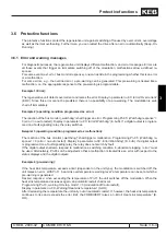
5
Error without AutoReset
Not set in case of errors when automatic restart is programmed.
6
Quick stopping / error
7
Pre-warning overload
ru.39 is an overload counter, which counts in 1%-steps. The COMBIVERT
switches off at 100%. When exceeding level Pn.09 (default 80%) overload
pre-warning is given. The behaviour in case of warning can be adjusted with
Pn.08 (warning OL stop. mode).
8
Pre-warning power stage over-
heating
Overtemperature pre-warning (OH)! Depending on the power unit the COM-
BIVERT switches off between 60… 95°C heat sink temperature. The pre-
warning is output, if the OH-warning level (Pn.11) is reached (default 70°C).
The behaviour in case of warning can be adjusted with Pn.10 (warning OL
stopping mode).
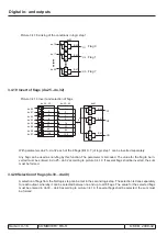
9
Overeating of the commutation
throttle
10
Overtemperature protection of
the commutation throttle
24
Act. load > level
25
AC input current (absolute
value) > level
26
Reference DC voltage > level
27
DC voltage > level
37
Timer 1 > level
ru.43 „timer 1 display“ respectively ru.44 „timer 2 display“ > switching level
38
Timer 2 > level
41
Modulation on
set, if the modulation is active
42
ANOUT3 PWM
Output of the analog signal ANOUT 3 respectively ANOUT 4 as PWM signal.
The cycle duration is adjusted with An.46 or An.52.
43
ANOUT4 PWM
44
Inverter state (ru.0) = level
Number of the state (e.g. 18 at error! watchdog) = switching level
45
Power module temperature
(ru.38) > level
Power module temperature (ru.38) > switching level
46
External temperature > level
48
DC output current > level
further on next side
Summary of Contents for combivert R6-S
Page 1: ...APPLICATION MANUAL Mat No Rev 00R6SEA K130 1 A GB KEB COMBIVERT R6 S Version 1 3 ...
Page 2: ...Page 1 1 2 COMBIVERT R6 S KEB 2008 02 Introduction ...
Page 4: ...Page 1 1 4 COMBIVERT R6 S KEB 2008 02 Introduction ...
Page 14: ...Page 1 2 6 COMBIVERT R6 S KEB 2008 02 Product overview ...
Page 28: ...Page 2 1 6 COMBIVERT R6 S KEB 2008 02 Fundamentals ...
Page 34: ...Page 2 2 6 COMBIVERT R6 S KEB 2008 02 Password structure ...
Page 116: ...Page 3 8 2 COMBIVERT R6 S KEB 2008 02 Special functions 3 8 1 Program timer counter 3 8 3 ...
Page 130: ...Page 3 9 10 COMBIVERT R6 S KEB 2008 02 Define CP Parameters ...
Page 140: ...Page4 2 2 COMBIVERT R6 S KEB 2008 02 Start up ...
Page 144: ...Page4 2 6 COMBIVERT R6 S KEB 2008 02 Start up ...
Page 150: ...Page 5 1 6 COMBIVERT R6 S KEB 2008 02 Error assistance ...
Page 158: ...Page 6 1 8 COMBIVERT R6 S KEB 2008 02 Project design ...
Page 160: ...Seite 7 1 2 COMBIVERT R6 S KEB 2008 02 Annex 7 1 1 Keyword index 7 1 3 ...
Page 166: ......
Page 167: ......


