


Seite 1.3 - 6
COMBIVERT R6-S
© KEB, 2008-02
Hardware
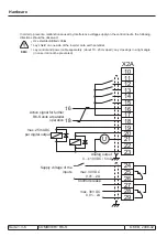
In order to prevent a malfunction caused by interference voltage supply on the control inputs, the following
directions should be observed:
EMC
•
Use shielded/drilled cables
•
Lay shield on one side of the inverter onto earth potential
•
Lay control and power cable separately (about 10...20 cm apart); Lay crossings in a right angle
(in case it cannot be prevented)
U
X2A
10
11
12
13
14
15
16
17
18
16
18
19
20
21
22
23
24
25
26
27
28
29
max. 25 mA DC
per digital output
Analog output
0…±10 V DC / 5 mA
max. 30 V DC
0,01…2 A
max. 30 V DC
0,01…2 A
Active signal for further
R6-S units at parallel
operation
Supply voltage of the
inputs
Control release
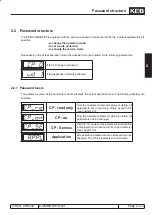
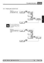
Summary of Contents for combivert R6-S
Page 1: ...APPLICATION MANUAL Mat No Rev 00R6SEA K130 1 A GB KEB COMBIVERT R6 S Version 1 3 ...
Page 2: ...Page 1 1 2 COMBIVERT R6 S KEB 2008 02 Introduction ...
Page 4: ...Page 1 1 4 COMBIVERT R6 S KEB 2008 02 Introduction ...
Page 14: ...Page 1 2 6 COMBIVERT R6 S KEB 2008 02 Product overview ...
Page 28: ...Page 2 1 6 COMBIVERT R6 S KEB 2008 02 Fundamentals ...
Page 34: ...Page 2 2 6 COMBIVERT R6 S KEB 2008 02 Password structure ...
Page 116: ...Page 3 8 2 COMBIVERT R6 S KEB 2008 02 Special functions 3 8 1 Program timer counter 3 8 3 ...
Page 130: ...Page 3 9 10 COMBIVERT R6 S KEB 2008 02 Define CP Parameters ...
Page 140: ...Page4 2 2 COMBIVERT R6 S KEB 2008 02 Start up ...
Page 144: ...Page4 2 6 COMBIVERT R6 S KEB 2008 02 Start up ...
Page 150: ...Page 5 1 6 COMBIVERT R6 S KEB 2008 02 Error assistance ...
Page 158: ...Page 6 1 8 COMBIVERT R6 S KEB 2008 02 Project design ...
Page 160: ...Seite 7 1 2 COMBIVERT R6 S KEB 2008 02 Annex 7 1 1 Keyword index 7 1 3 ...
Page 166: ......
Page 167: ......


