Page 3.2 - 16
COMBIVERT R6-S
© KEB, 2008-02
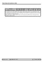
Operating and appliance data
Parameter
Addr.
R PG E
Min. value
Max. value Res.
[?]
Default
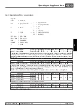
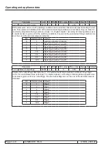
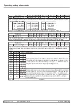
SY.11 Baud rate int. bus
000Bh
rw
-
+
3
10
1
-
5
The transmission speed between operator/inverter or PC/inverter is determined with the internal baud rate.
Following values are possible:
Value
Baud rate
Value Baud rate
Value
Baud rate
3
9,6 kBaud
6
55,5 kBaud
9
115,2 kBaud
4
19,2 kBaud
7
57,6 kBaud
10
125 kBaud
5
38,4 kBaud
8
100 kBaud
11
250 kBaud
After Power-On it is always started with 38.4 kBaud and dependent on the operator higher set.
Parameter
Addr.
R PG E Min. value
Max. value Res.
[?]
Default
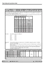
SY.32 Scope timer
0020h ro
-
-
0
65535
1
-
0
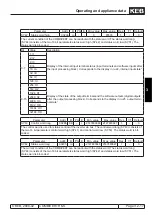
The scope timer generates a time period of 1 ms. This can be used by external programs, e.g. scope, to
represent
time patterns. The timer counts from 0...65535 and starts again with 0 after an overflow.
Parameter
Addr.
R PG E Min. value
Max. value Res.
[?]
Default
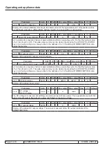
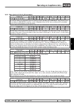
SY.41 Control word high
0029h rw
-
+
0
65535
1
-
0
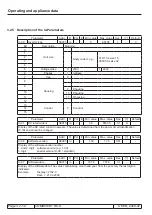
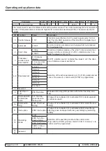
The control word is used for status control of the inverter via bus. The control word long (SY.43) consists of
the two 16 bit parameters control word high (SY.41) and control word low (SY.50). The status word is bit-
coded.
Bit
Function
Value
Description
16
I1
1: I1
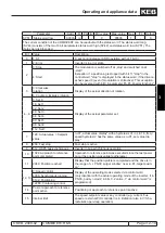
Corresponding input is set via the control word instead via hardware input.
These bits are only effective if the bit for the appropriate input is set in di.01
„select signal source“. Then the OR operation of this bit with the correspon-
ding bits of parameter di.02 " digital input setting" is valid.
17
I2
2: I2
18
I3
4: I3
19
I4
8: I4
20
IA
16: IA
21
IB
32: IB
22
IC
64: IC
23
Id
128: Id
24
O1
256: O1
Appropriate output is set via the control word or via the switching conditions.
Output signals O1, O2, R1 and R2 (visible in parameter ru.80) are OR ope-
rated with the appropriate bits of the control word. The connection occurs
according di.42 „inverted outputs “(inverting level for the output signals) and
before they are switched to the hardware outputs with do.51 „ hardware
output allocation“.
25
O2
512: O2
26
R1
1024: R1
27
R2
2048: R2
28...31
reserved
Summary of Contents for combivert R6-S
Page 1: ...APPLICATION MANUAL Mat No Rev 00R6SEA K130 1 A GB KEB COMBIVERT R6 S Version 1 3 ...
Page 2: ...Page 1 1 2 COMBIVERT R6 S KEB 2008 02 Introduction ...
Page 4: ...Page 1 1 4 COMBIVERT R6 S KEB 2008 02 Introduction ...
Page 14: ...Page 1 2 6 COMBIVERT R6 S KEB 2008 02 Product overview ...
Page 28: ...Page 2 1 6 COMBIVERT R6 S KEB 2008 02 Fundamentals ...
Page 34: ...Page 2 2 6 COMBIVERT R6 S KEB 2008 02 Password structure ...
Page 116: ...Page 3 8 2 COMBIVERT R6 S KEB 2008 02 Special functions 3 8 1 Program timer counter 3 8 3 ...
Page 130: ...Page 3 9 10 COMBIVERT R6 S KEB 2008 02 Define CP Parameters ...
Page 140: ...Page4 2 2 COMBIVERT R6 S KEB 2008 02 Start up ...
Page 144: ...Page4 2 6 COMBIVERT R6 S KEB 2008 02 Start up ...
Page 150: ...Page 5 1 6 COMBIVERT R6 S KEB 2008 02 Error assistance ...
Page 158: ...Page 6 1 8 COMBIVERT R6 S KEB 2008 02 Project design ...
Page 160: ...Seite 7 1 2 COMBIVERT R6 S KEB 2008 02 Annex 7 1 1 Keyword index 7 1 3 ...
Page 166: ......
Page 167: ......


