Page 6.1 - 4
COMBIVERT R6-S
© KEB, 2008-02
Project design
Control cabinet surface
Calculation of control cabinet surface:
Air flow rate with fan cooling:
P
V
—
‒
———
∆
T • K
3,1 • P
V
——
‒
——
∆
t
A =
[m
2
]
V =
[m
3
/h]
A
=
Control cabinet surface
[m
2
]
∆
t
=
temperature differential
(standard value = 20K)
[K]
K
=
coefficient of heat transmission
(standard value = 5)
P
V
=
power loss (see technical data)
V
=
air flow rate of fan
For more details please refer to the catalogs of the control cabinet manufacturers.
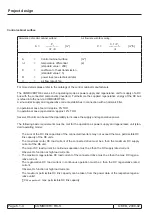
The COMBIVERT R6 serves in the operating mode as power supply and regenerative unit for supply of a DC
bus with the connected components (inverters). Furthermore the supplied regenerative energy of the DC bus
is refeed into the net via COMBIVERT R6.
A ‚sinusoidal‘ supply and regenerative current establishes in
connection with a harmonic filter.
In operational case ‚feed-in‘ approx. 8% THD.
In operational case ‚regeneration‘ approx.12% THD.
Several R6 units can be switched parallelly to increase the supply and regenerative power.
The following basic requirements must be met for the operation as power supply and regenerative unit (stan-
dard operating mode):
- The sum of the DC link capacities of the connected inverters may not exceed the max. permissible DC
link capacity of the R6 units.
- The maximum motor DC load
current of the connected drive must be ≤ than the maximum DC supply
current of the R6 unit.
- The motor DC load
current in continuous operation must be ≤ than the DC supply
rated current.
Observe OL function at high load currents.
- The maximum regenerative DC load
current of the connected drive must be ≤ than the max. DC regene
-
rative current.
- The regenerative DC load
current in continuous operation must be ≤ than the DC regenerative
rated
current.
Observe OL function at high load currents.
- The maximum permissible DC link capacity can be taken from the power data of the respective regene-
rative units!
∑ C
ZK capacitors
≤ max. permissible DC
link capacity
Summary of Contents for combivert R6-S
Page 1: ...APPLICATION MANUAL Mat No Rev 00R6SEA K130 1 A GB KEB COMBIVERT R6 S Version 1 3 ...
Page 2: ...Page 1 1 2 COMBIVERT R6 S KEB 2008 02 Introduction ...
Page 4: ...Page 1 1 4 COMBIVERT R6 S KEB 2008 02 Introduction ...
Page 14: ...Page 1 2 6 COMBIVERT R6 S KEB 2008 02 Product overview ...
Page 28: ...Page 2 1 6 COMBIVERT R6 S KEB 2008 02 Fundamentals ...
Page 34: ...Page 2 2 6 COMBIVERT R6 S KEB 2008 02 Password structure ...
Page 116: ...Page 3 8 2 COMBIVERT R6 S KEB 2008 02 Special functions 3 8 1 Program timer counter 3 8 3 ...
Page 130: ...Page 3 9 10 COMBIVERT R6 S KEB 2008 02 Define CP Parameters ...
Page 140: ...Page4 2 2 COMBIVERT R6 S KEB 2008 02 Start up ...
Page 144: ...Page4 2 6 COMBIVERT R6 S KEB 2008 02 Start up ...
Page 150: ...Page 5 1 6 COMBIVERT R6 S KEB 2008 02 Error assistance ...
Page 158: ...Page 6 1 8 COMBIVERT R6 S KEB 2008 02 Project design ...
Page 160: ...Seite 7 1 2 COMBIVERT R6 S KEB 2008 02 Annex 7 1 1 Keyword index 7 1 3 ...
Page 166: ......
Page 167: ......

