Seite 3.6 - 6
COMBIVERT R6-S
© KEB, 2008-02
Protective functions
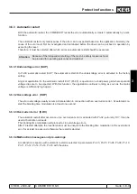
3.6.1.7 Bus error
The COMBIVERT contains two watchdogs that monitor the communication between an external bus, the ope-
rator, and the inverter control.
With parameter Pn.05 „Response to
E.bus“, the response to a watchdog error is defined. Dependent on the
chosen adjustment, either „Error! Watchdog“ (E.buS) or „Warning! Watchdog error“ (A.buS), is issued or a war-
ning message via a digital output is generated.
Watchdog-time (Pn.06)
This watchdog monitors the communication at the operator interface. With an activated watchdog, the response
set under Pn.05 is triggered after expiration of an adjustable time (0.01...40 s) without received telegrams.
By input of the value „0: off“ the function is
deactivated.
HSP5 Watchdog-time (SY.09)
The HSP5 watchdog function monitors the communication of the HSP5 interface (control card - operator; or
control card - PC). The adjusted response in Pn.05 is released if no telegrams after expiration of an adjustable
time (0.01...10 s)
are received. Value „0: off“
deactivates the function.
3.6.1.8 Set selection error
Sets can be locked with Fr.03 „Parameter set lock“. If a disabled set is selected, the inverter remains in the old
set, i.e., no set change occurs.
The response to the selection of a locked set is defined via Pn.18 „E.Set
stopping mode“. In the factory setting,
the error
„39: Error! Parameter set
selection“ (E.Set) is triggered. For Pn.18 = 1...5 a
malfunction „102: Warning!
Set selection error“ (A.Set) is generated. For Pn.18 = „6:
Function disabled“, the drive continues running in the
old set without message.
3.6.1.9 Hardware error
On some inverter types monitorings for the internal hardware (e.g., switch-mode power supply or loading shunt
relay) are integrated. If one of these monitoring circuits reports an error, „12: general power circuit error“ (E.
PU) is triggered.
Error Messages
E.EEP Error! EEPROM
defective
21 After reset the operation is again possible (without storage in the
EEPROM).
E.LSF Error ! load shunt fault
15
Error: Load-shunt relay has not picked up, occurs for a short
time during
the switch-on phase, but must automatically be reset immediately. If
the error message remains the following causes may be applicable:
- load-shunt defective
- input voltage wrong or too low
- high losses in the supply cable
E.Puci Error ! power circuit
unknown
49 During the initialization the power circuit could not be recognized or
was identified as invalid.
E.Puch Error ! power unit
changed
50
Power circuit identification was changed; with a valid power circuit this
error can be reset by writing to SY.3. If the value displayed in SY.03 is
written, only the power-circuit dependent parameters are reinitialized.
If any other value is written, then the default set is loaded. On some
systems after writing Sy.03 a Power-On-Reset is necessary.
E.PUIN Error ! power circuit
coding
14
Error: Software version for power circuit and control card are different.
Error cannot be reset.
Summary of Contents for combivert R6-S
Page 1: ...APPLICATION MANUAL Mat No Rev 00R6SEA K130 1 A GB KEB COMBIVERT R6 S Version 1 3 ...
Page 2: ...Page 1 1 2 COMBIVERT R6 S KEB 2008 02 Introduction ...
Page 4: ...Page 1 1 4 COMBIVERT R6 S KEB 2008 02 Introduction ...
Page 14: ...Page 1 2 6 COMBIVERT R6 S KEB 2008 02 Product overview ...
Page 28: ...Page 2 1 6 COMBIVERT R6 S KEB 2008 02 Fundamentals ...
Page 34: ...Page 2 2 6 COMBIVERT R6 S KEB 2008 02 Password structure ...
Page 116: ...Page 3 8 2 COMBIVERT R6 S KEB 2008 02 Special functions 3 8 1 Program timer counter 3 8 3 ...
Page 130: ...Page 3 9 10 COMBIVERT R6 S KEB 2008 02 Define CP Parameters ...
Page 140: ...Page4 2 2 COMBIVERT R6 S KEB 2008 02 Start up ...
Page 144: ...Page4 2 6 COMBIVERT R6 S KEB 2008 02 Start up ...
Page 150: ...Page 5 1 6 COMBIVERT R6 S KEB 2008 02 Error assistance ...
Page 158: ...Page 6 1 8 COMBIVERT R6 S KEB 2008 02 Project design ...
Page 160: ...Seite 7 1 2 COMBIVERT R6 S KEB 2008 02 Annex 7 1 1 Keyword index 7 1 3 ...
Page 166: ......
Page 167: ......

