background image

Kavo 3D eXam ®  Operators’ Manual

k990400    September 19, 2007

10-4

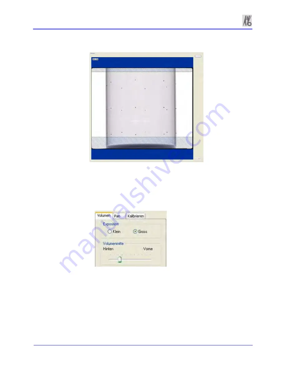
18. The BB Phantom image is displayed, shown below.

19. Ensure that the phantom is centered, level, and 

all

 BBs (dots) 

appear in the FOV. If required, make adjustments and click 

Preview

 again. Repeat as required.

To move the phantom to the right or left on the Preview screen, 
use the 

Back / Front 

feature on the Volume tab and then return 

to the Calibration tab.

20. When BB Phantom is centered and level, click 

Calibrate 

from 

the Geometry Calibration window.

21. Click 

OK

 to start the X-ray exposure.

Back

(Volume Center)

Front

(Volume Center)

Summary of Contents for 3D eXam

Page 1: ...k990400 September 19 2007 Cone Beam Volumetric Tomography and Panoramic Dental Imaging System Operators Manual...

Page 2: ...iences International please write call or fax to Imaging Sciences International at the above address This documentation has been drafted approved supplied in the English Language Imaging Sciences Inte...

Page 3: ...ngs Cautions and Notes 2 1 Safety Precautions 2 2 Electrical Fire Hazard 2 2 Mechanical Hazards 2 3 Laser Beam Hazards 2 3 Radiation Safety 2 3 Emergency Stop 2 4 Warning System 2 4 Interlock System 2...

Page 4: ...11 Chapter 7 Reconstruction of Anatomy Preview Screen 7 1 Adjusting the Panoramic View 7 3 Contour Line Setup 7 4 Removing Circumference Artifacts 7 6 Adjusting MIP Centerline and Image Type 7 6 Selec...

Page 5: ...Folder 9 5 Reporting 9 6 Run Report 9 6 Create New Report 9 7 Modify Existing Report 9 11 Chapter 10 Calibration and Quality Assurance Panel Calibration 10 1 Geometry Calibration 10 3 QA Phantom Test...

Page 6: ...cifications 12 1 Power Requirements 12 2 Power Cords 12 2 Environmental Specifications 12 3 Operating 12 3 Transportation and Storage 12 3 Acquisition Computer 12 3 Patient Support Chair 12 4 Disposal...

Page 7: ...Menu A 15 Appendix B iCATVision iCATTransfer Installation iCATVision B 1 File Structure Setup B 1 Install iCATVision B 2 iCATVision Setup B 3 iCATTransfer B 4 Install iCATTransfer B 4 iCATTransfer Pa...

Page 8: ...September 19 2007 viii Implant Planning Screen C 3 Panoramic Map C 4 Axial Slice Position C 4 Ortho Screen C 5 MPR Screen C 5 Install Case Studies from CDs C 6 TMJ Planning Screen C 6 Create Export C...

Page 9: ...office environment The Gantry is an open design that allows Patients to sit upright during a procedure An electric powered seat is built into the Gantry for proper Patient positioning KaVo 3D eXam Ima...

Page 10: ...amount of X ray energy delivered to the tissue CT imaging displays both high density tissue such as bone and soft tissue When interpreted by a trained Physician CT images provide useful diagnostic in...

Page 11: ...original warranty or thirty 30 days whichever is longer The warranty period is not extended as a result of purchasing any additional parts from ISI The original purchaser must promptly notify ISI in...

Page 12: ...ISI be liable for any special incidental or consequential damages based upon breach of warranty breach of contract negligence strict liability or any other legal theory Such damages include but are n...

Page 13: ...d that you read this manual thoroughly including all cautions and warnings This guide uses the following conventions to describe situations that are potential hazards to the Patient or Operator potent...

Page 14: ...al Fire Hazard Do not place any liquid or food on any part of the consoles or other modules of the system Observe all fire regulations Fire extinguishers should be provided for both electrical and non...

Page 15: ...with large diopter or mirrors increase eye hazard with this product Radiation Safety X rays are dangerous to both operator and others in the vicinity unless established safe exposure procedures are st...

Page 16: ...terminals 1 and 2 of the X Ray Interlock printed circuit board inside the Lower Control Center A relay contact capable of 250 volts 50 60 hertz and 3 amps is connected between these terminals When X r...

Page 17: ...nstalled jumper between terminals 3 5 of the X Ray Interlock printed circuit board inside the Lower Control Center and connect door switches and or emergency stop switches in series between terminals...

Page 18: ...Kavo 3D eXam Operators Manual k990400 September 19 2007 2 6 System Labels The following labels are attached to the system...

Page 19: ...OWER indicator lights to show that the Gantry is ON OFF removes power from the Gantry and the POWER indicators go OFF EMERGENCY STOP immediately halts all X ray and scanning activities SCAN initiates...

Page 20: ...uct ALIGNMENT LIGHT pressing the button turns ON the laser alignment lights for three seconds Press and hold the button for three seconds turns the laser lights ON permanently until the button is agai...

Page 21: ...s launched 3 Power up Gantry press the ON button on the Main Control Box The POWER indicator on the Main Control Box and Gantry light NOTE Although the system is now ready to scan the Ready indicator...

Page 22: ...ame field Click OK or Overwrite an existing Workup by clicking an existing Workup Name 2 Power OFF Gantry press the OFF button on the Main Control Box The Gantry shuts down and the POWER indicators on...

Page 23: ...ed This window lists all the Patients that were entered into the database When a Patient is selected highlighted that Patient s scanned images are listed in the window beneath the Patient List Patient...

Page 24: ...File New Patient 2 Click Add button 3 Enter Patient data in the corresponding fields as applicable A unique Patient ID must be added such as a Patient file number or social security number Click the...

Page 25: ...ther data has been acquired for this Patient by selecting the Done entry 4 Click OK to add Patient data 5 Click OK to close dialog box Edit Patient Details To edit Patient details 1 From the Main menu...

Page 26: ...not scanned HIS RIS Hospital Info System Radiology Info System imported Patient Data PMS Practice Management System imported Patient Data Manual Patient Data entered manually 3 Click highlight the Pa...

Page 27: ...log box Only Patients whose data matches the selected criteria are displayed Done Patient Data entered and scanned Queued Patient Data entered but not scanned HIS RIS Hospital Info System Radiology In...

Page 28: ...Patient List can be hidden by selecting Tools Hide Patient from the Main menu When hidden the Patient list appears as shown below To display the Patient list select Tools Show Patient from the Main me...

Page 29: ...ne Patient Data entered and scanned Queued Patient Data entered but not scanned HIS RIS Hospital Info System Radiology Info System imported Patient Data PMS Practice Management System imported Patient...

Page 30: ...Kavo 3D eXam Operators Manual k990400 September 19 2007 5 8...

Page 31: ...for Patients that are taller than 6 2 2 With the gate opened have the Patient seated in the chair facing forward The Patient should be seated comfortably with hands in lap HEAD SUPPORT BACKPLATE CHIN...

Page 32: ...ams can cause optical damage Do not stare into the laser beam Instruct the Patient to avoid looking into the beam The use of optical instruments such as eyeglasses with large diopter or mirrors increa...

Page 33: ...e at the chin Acquisitioning Once Patient data is entered and the Patient is properly positioned acquisitioning can begin 1 To acquire a new acquisition do one of the following Once data is entered fo...

Page 34: ...indow is displayed 2 If desired enter any remarks in the Study Remarks text field 3 From the Quick Picks drop down list box select a standardized acquisition setup or create a new one see details belo...

Page 35: ...cted teeth periodontal condition and other anatomy requiring detailed visualization Portrait Mode should be used for the Height of Reconstructed Volume for adult Patients where cephalometric data is r...

Page 36: ...selected for young children and small elderly females Large is for a normal size adult or large child head size 5 Select Resolution by using the corresponding drop down list box In general the lower t...

Page 37: ...less 6 Adjust the Volume Center slide control to select the position of the x ray sensor front to back 7 Select the Height of Reconstructed Volume from the drop down list to indicate the portrait or...

Page 38: ...D eXam Operators Manual k990400 September 19 2007 6 8 The following dialog box is displayed 2 Click OK The system proceeds to take a Static Exposure Quick Ceph The resulting image is displayed on the...

Page 39: ...tructed to hold still swallow before the scan take shallow breaths during the scan and may want to close his her eyes so he she won t be tempted to follow the turret with their eyes during the scan WA...

Page 40: ...ewinds before releasing the Patient from the machine The software immediately begins the reconstruction of the image data The time required to reconstruct depends on the Scan Time and Voxel size selec...

Page 41: ...Locator 2 Press the Alignment Light button on the Gantry Front Panel to display lasers Lasers are available while the Volume tab is selected not PAN 3 Ensure that the Vertical Laser intersects the no...

Page 42: ...Rest and Bite Tip Holder into the Positioning Block as shown below 4 Adjust Patient height to where the Patient s chin is on the Chin Rest but keeping the Erect posture NOTE The front to back Patient...

Page 43: ...zontal Laser Then have the Patient tilt their head downward approximately 10o Refer to the illustration above for a visual of tilting the Patient Using the Sagittal Laser front center laser ensure tha...

Page 44: ...bserve and follow the safe exposure factors and operating instructions Do not operate this system unless you have received training to perform a procedure 12 Click the Capture button to start the test...

Page 45: ...mber 19 2007 Acquisitioning Scanning 6 15 15 The PAN scan runs a few minutes and then displays the reconstructed image 16 Adjust the Brightness Contrast by dragging the cursor across the image vertica...

Page 46: ...Kavo 3D eXam Operators Manual k990400 September 19 2007 6 16...

Page 47: ...aded to the preview screen While data loading is occurring a preview window appears in the center of the screen At the bottom right side of the iCATVision window the status of the data loading is disp...

Page 48: ...l through midline The Preview Screen is divided into seven views Patients in Database Patient Images Patient Detail View Panoramic View Sagittal View Coronal View Axial View Patients in Database lists...

Page 49: ...Double clicking on the Coronal View brings up the MPR Screen Axial View controls the image displayed in the Panoramic View Distance and Hounsfield Unit measurements are taken on this view Double clic...

Page 50: ...Contour Line Setup Contour Lines are used to mark the Maxilla and Mandible in the Sagittal and Coronal Views on the preview screen Maxilla is a red line Mandible is a green line Both the Maxilla and M...

Page 51: ...ronal Views on the preview screen To do this do the following 1 On an image view on the Preview screen right click and select Add Remove Contourline 2 Click check box corresponding to the Contour Line...

Page 52: ...em software Center Line Position click and drag the Center Line Position tool moves the displayed centerline of the selected image This changes the selected position of subordinate images as applicabl...

Page 53: ...ark to the right of the corresponding menu item Adjusting Brightness and Contrast All views include a window level Brightness Contrast cursor tool By default this cursor is displayed When cursor appea...

Page 54: ...creen until the cursor becomes an X 2 While the cursor is an X click the left mouse button You are returned to the preview screen This can also be performed by clicking Level Up on menu bar Filter Set...

Page 55: ...filter setting is applied to the corresponding image Setting Filters for One or More Image Types To change the filter setting for one or more image types 1 From the Main menu select Tools Filter Sett...

Page 56: ...d Units Shape Region for all image views These measurements calculate and display the average Mean grayscale level of the area enclosed from 1000 to 3000 where 0 equals the density of water The Standa...

Page 57: ...tional measurements are displayed in varying colors so that they can be easily associated with the selected image area To switch off the hu cursor 1 Right click the image A popup window appears 2 Clic...

Page 58: ...Measurements becomes available Reactivate All Measurements restores all of the inactivated measurements to the selected view Distance The system software allows making distance linear measurements for...

Page 59: ...asurement Measurement statistics appear in the upper left corner of the image 3 Repeat steps 2 and 3 to take additional measurements A maximum of nine distance measurements can be taken at a time in a...

Page 60: ...removed and select Remove Measurement Remove All Measurements removes all measurements from selected view Inactivate All Measurements grays out all measurement indicators and removes the measurements...

Page 61: ...e is rotated release the mouse The grid is no longer present To complete the rotation of the entire data set 4 Right click the image and select Rotate Volume now The menu closes and the software recal...

Page 62: ...d select Open Output Folder Microsoft Internet Explorer opens to the selected directory Saving and Loading Workups Once Patient data is acquired it is reconstructed Reconstruction allows you to make v...

Page 63: ...in the Workup Name field c Click OK The dialog box closes and the new workup is displayed on the Select a Workup dialog box or a Overwrite an existing workup by clicking an existing Workup Name b Clic...

Page 64: ...dialog box appears To save the changes made click Yes The Select a Workup dialog box appears Continue the save procedure as described above Load an Existing Workup To load an existing workup for a Pat...

Page 65: ...September 19 2007 Reconstruction of Anatomy 7 19 Delete an Existing Workup To delete an existing workup 1 Right click any image on Preview screen and select Save This Workup 2 Right click the Workup t...

Page 66: ...Kavo 3D eXam Operators Manual k990400 September 19 2007 7 20 3 Click Yes The dialog box closes and the selected Workup is deleted 4 Click Cancel to close the Select a Workup dialog box...

Page 67: ...ng a corresponding view on the Preview Screen Panoramic View double click displays the Implant Planning Screen Sagittal View double click displays the Ortho Ceph Screen Coronal View double click displ...

Page 68: ...xial views which are represented on the axial slice position view and modify the criteria used to generate the axial views lower right 3D Model View lower left shows a three dimensional representation...

Page 69: ...adjust the image displayed on the panoramic map view The blue hash mark represents the center line of the axial slices displayed on the cross section views The corresponding center cross section slice...

Page 70: ...iew to modify the position of the cross section views which are represented on the axial slice position view and modify the criteria used to generate the cross section views at the lower right of the...

Page 71: ...cal toolbar to adjust the slice thickness displayed on the cross section views Changes made here are reflected on the cross section views 3 Individual cross section images can be zoomed in by double c...

Page 72: ...the Ortho screen displays a single item popup menu Clicking Tag Airways generates a 3D view of the airways for the patient in the blank view In addition the tagged airway data is displayed in the view...

Page 73: ...airway view and select Untag Airways MPR Screen Double click Coronal View on Preview Screen displays MPR Screen The MPR Screen allows you to scroll through the Axial upper left Sagittal upper right an...

Page 74: ...ical toolbars to adjust the slice thickness of the corresponding color coded view To view the result of a linear slice 1 To view a linear slice right click the view and select Line A pointer cursor is...

Page 75: ...sulting slice is displayed in the view at the lower right of the MPR Screen 3 To reposition the line drag the end points of the line To explore additional cut planes in an animated consecutive fashion...

Page 76: ...to position the cut planes slice as desired Cursor changes to a film icon 6 Right click image and select Explore Speed 7 Enter desired animation speed in Movie Playback Speed field 8 Click OK 9 Click...

Page 77: ...TMJ Screen TMJ Screen enables condyle mapping and creating corresponding coronal slice views To use the TMJ Screen 1 If necessary pan the Axial SMV View upper left down in the window to see the condyl...

Page 78: ...lbars to adjust the slice thickness of the cross section views To create lateral slices 5 Drag the center blue circles on the Axial View to move the corresponding Condyle Map 6 Drag the yellow and blu...

Page 79: ...s This procedure is used to determine where these DICOM image files are to reside 1 From the top Main menu select Tools Setup DICOM Database Root Folder contains patient data that is required for crea...

Page 80: ...ot presently used Check Read Write Access to Image Database This function tests the ability of iCATVision to read write to the image root folder iCATVision requires Write Access to this path to store...

Page 81: ...tandard for digital images which is a means for medical imaging products to share images The following process demonstrates how to convert patient data files into DICOM images for export To Export DIC...

Page 82: ...ntent the new files are stored to the folder replacing old files The Destination field was setup at the start of this section 4 Click OK Done is displayed when the process is complete Create CD The in...

Page 83: ...rase CD RW This Erase CD option can only be used if using re writable CDs 1 From the top Main menu select Tools Create Export CD The CD Burner window is displayed shown above 2 Click Erase CD RW An op...

Page 84: ...ent information and text notes can also be inserted as required Once these reports are created and saved they are readily available for printing and distribution Patient reports can also be accessed f...

Page 85: ...st Allow time for the Patient Image to load 2 From the Main menu select Tools Reporting 3 Click Create New Report from the Options box 4 The Edit Fields box is displayed Enter all required Clinic and...

Page 86: ...Life Size used to depict the image in life size able to measure directly on the paper The drop down list box allows you to specify where the image originated For example if Left Top Corner is selecte...

Page 87: ...e image Insert Text Box 8 Select Insert Text from the Main menu or right click the report page and select Add Text 9 Select desired variable from the Change Variable list Holding down the CTRL key and...

Page 88: ...mouse button and dragging the cursor Cross Arrows used to move Text box Double Headed Arrow used to size Text box Add Page 13 Select Insert Page from the Main menu or right click a report page and sel...

Page 89: ...eport This function is used to edit reports that were previously created To create a new Patient Report 1 From the Main menu select Tools Reporting 2 Click Modify Existing Report from the Options box...

Page 90: ...Kavo 3D eXam Operators Manual k990400 September 19 2007 9 12...

Page 91: ...Landscape positions The entire calibration takes about 8 to 10 minutes to complete The process runs a five mode calibration as listed below Mode 0 4 x 4 Landscape Mode 1 2 x 2 Landscape Mode 2 2 x 2 P...

Page 92: ...m the field of view and click OK to start X ray exposure 7 Click OK 8 The Panel Calibration runs for about 10 minutes The progress of the scan is displayed on the Progress bar at the bottom of the Acq...

Page 93: ...mplete 11 Perform the Panel Calibration procedure listed above 12 Mount the Phantom Platform shown below 13 Ensure that the BB Phantom is level 14 Center the BB Phantom on the platform using the align...

Page 94: ...f required make adjustments and click Preview again Repeat as required To move the phantom to the right or left on the Preview screen use the Back Front feature on the Volume tab and then return to th...

Page 95: ...bove the green progress bar ensure the following Landscape Scan 24 Beads detected 24 Beads valid Portrait Scan 20 Beads detected at least 16 Beads valid 24 Click OK when the calibration completes NOTE...

Page 96: ...Phantom Test and QA Water Test This procedure is performed to check the High Contrast Spatial Resolution 1 Remove Chin Cup and insert Phantom Platform 2 Place QA Phantom on Platform Use a piece of foa...

Page 97: ...ck Add or right click an existing image from database and select Acquire Now If adding a new patient enter QA Test in the First Name field and Line Pair in the Patient ID field 7 Click OK to close the...

Page 98: ...achieve the proper height 13 To move the phantom to the right or left use the Back Front feature on the Volume tab and then return to the Calibration tab If required make adjustments and click Preview...

Page 99: ...k990400 September 19 2007 Calibration and Quality Assurance 10 9 17 The following preview screen is displayed...

Page 100: ...iew bottom image 3rd from the left 19 The image below is displayed In the upper right corner view slide the Vertical and Horizontal lines to the Line Pairs centers as shown below 20 Zoom Line Pair ima...

Page 101: ...sent within line pairs 10 11 and 12 Compare your image quality to the image shown above Your Line Pair 12 should have the same image quality definition as the 13 Line Pair displayed above or better Di...

Page 102: ...pper left To zoom start at the lower right corner of the image and drag the cursor across the image For consistency ensure that the slice selection to be measured is setup as follows a Right click top...

Page 103: ...ed within the QA phantom Note to achieve an accurate measurement boxes should be as large as possible without touching the circle diameter 31 Note and record the Hounsfield value of each material See...

Page 104: ...of rotation and the horizontal laser line is located across the center of water depth 5 Start test by selecting File New Patient from the Main menu 6 From the Patient Information Panel click Add or r...

Page 105: ...f the water height Adjust the Phantom Platform to achieve the proper height Use the menu Back Front arrow slide to adjust the phantom side to side position If required make adjustments and click Previ...

Page 106: ...Operators Manual k990400 September 19 2007 10 16 13 The red dotted line in the upper right screen should appear in the middle of the water height Use the Center Line Positioning tool to make the heigh...

Page 107: ...terest in the center of Water and also the Air outside area of the water bowl as shown above HU Area box size should be approximately 1000 0 mm2 inside the Water Phantom area 400 0 mm2 outside the Wat...

Page 108: ...e Level Test right click the HU data upper right corner of image and select Remove all measurements 19 Right click the image and select HU Statistics from the menu Use the Region Tool to define a ROI...

Page 109: ...ording values a fifth ROI is required from the center of the water area The fifth measurement replaces the first measurement since four measurements is the limit 22 Note and record the Mean and SD val...

Page 110: ...alls facing up 4 Insert Bite Tip into the phantom front mounting hole to lock phantom into place 5 Press the Alignment Light button on the Gantry Front Panel to display lasers Use the Horizontal Laser...

Page 111: ...e Patient Information box 9 Click the Pan tab in the Acquisition window and select Exposure Large 10 Click the Capture button to start the test 11 The system moves approximately 1 4 rotation to the Ho...

Page 112: ...runs a few minutes and then displays the reconstructed image 14 Adjust the Brightness Contrast by dragging the cursor across the image vertical horizontal All seven metal balls should become visible...

Page 113: ...axial lasers intersect This is in the lower center of the detector 2 Perform a 9 second 13 cm 0 4 voxel scan and record time and dose from meter 3 Repeat step 2 for 27 seconds and record Measured Dose...

Page 114: ...presentative Imaging Sciences International LLC Guy Long 1910 North Penn Road Imaging Sciences International LLC Hatfield PA 19440 Western Europe Service Centre United States of America Corinium Indus...

Page 115: ...JIS T0601 CE MDD 93 42 EEC IEC EN 60601 1 LVFS 2003 11 Swedish regulation transposing the MDD 93 42 EEC IEC EN 60601 1 1 CMDCAS Canadian Medical Device Regulation IEC EN 60601 1 2 ISO 10993 1 2003 IEC...

Page 116: ...Canada Medical Device Keyword Index for X ray equipment and IEC standards 60601 2 7 and 60601 2 28 The following class of equipment was determined Protection against electric shock Class I Applied pa...

Page 117: ...rious bodily injuries to Patients and persons in the surrounding area Adequate precautions must always be taken to avoid or reduce exposure to the useful beam as well as scattered radiation Refer to t...

Page 118: ...f 41 7 mA min week 50 scans per week yielding a workload of 83 3 mA min week Total scan time 9 seconds Location Distance in Feet meter Exposure mR Exposure R 10 scans wk mR wk 25 scans wk mR wk 50 sca...

Page 119: ...11 110 1 10 2 75 5 50 9 2 74m 0 036 36 0 36 0 90 1 80 135o 3 0 91m 0 031 31 0 31 0 78 1 55 6 1 82m 0 021 21 0 21 0 53 1 05 9 2 74m 0 012 12 0 12 0 30 0 60 180o C 3 0 91m 0 124 124 1 24 3 10 6 20 6 1...

Page 120: ...a minimum of two meters or behind a properly shielded permanent barrier A viewing window or alternative method such as a mounted mirror should be present to enable the X ray Operator to view the Patie...

Page 121: ...ead Phantom and used a light localizer to position phantom in center of scan so slice cuts through the center of the phantom 2 Performed a Capture view to assess the alignment 3 Performed a scan 4 Use...

Page 122: ...hicknesses is not required as this is not applicable to the 17 19 Cone Beam Volumetric Tomography technology 10 Repeat for chamber in peripheral locations 1 cm interior to the surface of the phantom w...

Page 123: ...11 7 Sensitivity Profile For the ultra high resolution mode when the bead SIZE in the phantom is scanned the following sensitivity profile is obtained mm Hounsfield value 1 2752 2 3104 3 2560 4 3104...

Page 124: ...semblies Operator Data Available focal spot sizes mm 0 5 Available target angles 15 Anode construction Vacuum cast copper with tungsten target Cathode construction Vacuum tube nickel with tungsten fil...

Page 125: ...ied Sige Phase Bi polar FILAMENT CURRENT AMP TUBE CURRENT mA FILAMENT VOLT AMP HARACTERISTICS 60 Hz AC DC VOLTS AMPS ANOD OOLING CURVE ANODE HEAT STORAGE AACITY HU X 1000 TIME IN MINTS H U Heat Unit k...

Page 126: ...Kavo 3D eXam Operators Manual k990400 September 19 2007 11 10...

Page 127: ...cations in order to have the focal spot to skin distance as large as possible Minimum Filtration at 120 kVp mm of aluminum equivalent 10 mm or greater Maximum Rated Continuous Tube Operation 130 kVp 0...

Page 128: ...x 6 67 inches height maximum 23 2 cm diameter x 17 cm height maximum Note Maximum values can be collimated down Primary Reconstruction Less than 2 minutes for 27 sec scan 0 4 voxel Secondary Reconstr...

Page 129: ...torage 32 to 104 degrees Fahrenheit 0 to 40 degrees Celsius 30 to 80 humidity Acquisition Computer Minimum Specifications for Acquisition Computer Provided with the System Pentium 4 Processor 3 8 GHz...

Page 130: ...X ray source assembly image sensor and all electronic circuits should be regarded as non environmental friendly waste product Extension Cords Do not use any extension cords which are not provided with...

Page 131: ...onment Guidance IEC 61000 4 2 Electrostatic Discharge ESD 6 kV Contact 8 kV Air Floors should be wood concrete or ceramic tile If floors are synthetic the relative humidity should be at least 30 EFT I...

Page 132: ...tions equipment Maximum Output Power Watts Separation 150 kHz to 800 MHz Separation 800 MHz to 2 5 GHz 0 01 15 in 38 cm 30 in 76 cm 0 1 15 in 38 cm 30 in 76 cm 1 46 in 117 cm 8 ft 2 4 m 10 12 ft 3 7 m...

Page 133: ...EN 60601 1 4 CSA C22 2 No 601 1 IEC EN 60601 2 32 JIS Z4701 IEC EN 60601 2 44 JIS Z4703 IEC EN 60825 1JIS T0601 JIS T0601 CE MDD 93 42 EEC IEC EN 60601 1 LVFS 2003 11 Swedish regulation transposing t...

Page 134: ...PONSIBILITY IN THOSE CASES WHERE NON COMPLIANCE WITH THE STANDARD RESULTS FROM THE USER S FAILURE TO HAVE THE MANUFACTURER S RECOMMENDED MAINTENANCE PERFORMED The actual maintenance inspection and con...

Page 135: ...ification Label X X Warning and Indicators X X Oil Leaks X X Physical Damage X X Mounting System Stability X X Beam Limiting Device Physical Damage X X Certification Label X X X Ray Controller Timer X...

Page 136: ...r 200 Volt Systems K1304 0 Patient E stop Box K1305 Patient Alignment Panel K1306 0 Operator Control Box 1539 Laser Cross 1540 Laser Straight Line 1543 Motor Beam Limiter 7 5 Stepper K1701 0 Isolation...

Page 137: ...1 10 Glide 1000179 4 11 Control Box 1306 0 1 12 Chair Patch Cable 1520 1 13 Cable Clips 101 6 6 14 Head Rest 27 0 1 15 Head Band 27 1 100 16 Pan Phantom 12 0 1 17 Phantom Assembly 14 1 0 1 18 Line Pa...

Page 138: ...Kavo 3D eXam Operators Manual k990400 September 19 2007 12 12 System Gantry Dimensions SIDE VIEW TOP VIEW FRONT VIEW...

Page 139: ...Three Dimensional Volume Rendering 3DVR Open Database 3 DVR is a standalone program which runs independently and is not part of iCATVision 1 To open DVR Diagnostic Volume Rendering double click the DV...

Page 140: ...n DICOM format If importing a case from iCATVision make sure to export the case in DICOM3 Multi File format 2 Click Open Dataset a browse window is displayed 3 Select the drive folder for the DICOM da...

Page 141: ...d DVR In this sample it is slice 10 of 256 To scroll through each slice 1 Click Paging Radio button 2 Drag the cursor either UP or DOWN to scroll through the axial slices Dragging the cursor upward sc...

Page 142: ...vate the ROI tool 1 Click ROI Radio button 2 Drag cursor to create a box around region of interest Release the mouse button to move box then click again to complete the box Calculated items are displa...

Page 143: ...distance tool measures linear distance To activate Distance tool 1 Click Distance radio button 2 Drag cursor from point to point to create a measurement line see below in green Linear measurement is...

Page 144: ...e Patient Chin Cup that may appear in the scan See the sample below Patient Chin Cup highlighted in blue To activate Identify tool 1 Click Identify Box The 3DVR Setup window is displayed and the dense...

Page 145: ...er in the box Remove Object To remove a piece of anatomy from image 1 Click the Remove Object box to enable checkmark 2 Then click the object of interest highlighted in blue 3 Close 3DVR Setup window...

Page 146: ...k for a region that has relatively even grayscales 3 At this location enable the ROI function 4 Drag the cursor in the area between the dental arch making sure not to include any teeth or bone This di...

Page 147: ...n Offset which currently has a value of 0 7 Click OK View Volume View Volume allows viewing all 3 projections of the 3D data Axial Coronal and Sagittal Also enables the creation of 3D Renderings Enabl...

Page 148: ...he Axial Coronal and Sagittal views are all in Radiographic mode NOTE Window Level can be adjusted in each of the 3 views by dragging the cursor in each window MIP mode Maximum Intensity Projection vi...

Page 149: ...of interest in the Coronal and Sagittal views Again the selected data is used to calculate the 3D image Once the area of interest is determined the 3D image can be displayed by utilizing the VR Funct...

Page 150: ...te a 3D Image 1 From the first View drop down menu select a direction to display The choices are AP Anterior Posterior PA Posterior Anterior LL Left Lateral RL Right Lateral Up Down 2 From the second...

Page 151: ...ample the entire volume data is selected in all 3 views Below is a sample of a 3D image calculated from the selected volume area seen below Sample of View Types Each View Type has its own Parameters w...

Page 152: ...D image to Full Screen Right click on the 3D image and select View Full Screen PAN Move the 3D image within the window by dragging cursor on image Zoom Zoom 3D image Drag cursor on image UP to Zoom OU...

Page 153: ...age in current working folder adds jpg extension The current working folder is the folder opened from the Open Dataset Save Grayscale to TIFF Saves 3D image in current working folder adds tiff extensi...

Page 154: ...entire computer screen All the same manipulation functions and 3D options are used in this display Right click to display Pop Up menu to utilize functions To return to the original viewing format pres...

Page 155: ...limit on usage and the number of copies File Structure Setup 1 On the iCAT Acquisition Computer create an iCATVision folder under the C drive 2 Create a subfolder under iCATVision called iCATVision Wa...

Page 156: ...AT Acquisition Computer s C drive under the iCAT Vision Folder Create a new Folder 1 Open the folder where the new folder is to reside 2 Right click and select New Folder 3 Type the name for the new f...

Page 157: ...the C drive or on a networked drive Setup is the same on all networked and non networked computers or workstations 3 A prompt to restart iCATVision software is displayed click OK NOTE It is currently...

Page 158: ...der The Image Root folder typically resides on a server or another central storage location If the computers are on the same network as the iCATTransfer then there is direct access to the patient imag...

Page 159: ...Agreement and then follow the instructions below iCATTransfer Setup The program must be configured to watch for exported DICOM data from iCAT in order to authenticate and transfer it to the image root...

Page 160: ...3 Under Image Root Folder Primary Destination Browse to iCATVision Root folder and select This is most likely on a server central storage location 4 Click Start This saves the preset Watch and Root d...

Page 161: ...k990400 September 19 2007 B 7...

Page 162: ...Kavo 3D eXam Operators Manual k990400 September 19 2007 B 8...

Page 163: ...k990400 September 19 2007 B 9...

Page 164: ...Kavo 3D eXam Operators Manual k990400 September 19 2007 B 10...

Page 165: ...ocation 1 2 3 5 6 7 4 REMINDER Images are displayed as if you are looking at the patient from the front TO DISPLAY PATIENT IMAGE 1 Click Patient Name 2 Click Patient Scans DISPLAYED VIEWS 3 Patient St...

Page 166: ...Filter Settings Reset to Default Removing Circumference Artifact Circumference Artifact are seen visually in the Preview Screens as horizontal lines in the Coronal and Sagittal images and a white part...

Page 167: ...LS All views except the 3D Model have Brightness Contrast Rotate Drag Zoom and Pan 3D Model only has Rotate Back Tool to exit out of a planning screen back to the Main Display move cursor to the very...

Page 168: ...this tool to adjust slice thickness of Panoramic View Drag the center tool to adjust Pan Focal Trough Click the bottom tool to change the Pan view from Radiographic to MIP 3 Vertical Tool Bar Drag thi...

Page 169: ...ank area 1 3 1 2 REMINDER Ortho Screen is acquired by double clicking Sagittal View from Preview window DISPLAYED VIEWS The Ortho Screen displays the Lateral Cephs in Radiographic and MIP mode as well...

Page 170: ...to be loaded Just click the patient name TMJ Planning Screen 1 Drag center tool to scroll up and down Sagittal view to locate condyles in the Axial view so you can see condyles properly for mapping 2...

Reviews: