40
English
5.906-736.0 Rev. 00 (07/15)
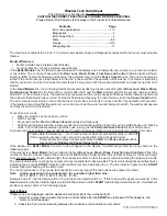
Colour assignment:
black: Water
red: Detergent
brown: Fuel (diesel)
blue: Cooling circuit motor
1 Antifreeze container
2 Liquid softener container with level switch and dosing
valve
3 Water inlet
4 Low-pressure hose drum
5 Water filter
6 Ball tap frost protection
3-way valve with positions:
- horizontal: Normal operation
- vertical: Frost protection mode
7 Float tank
8 Water shortage safeguard
9 Temperature sensor water float container
10 Stop cock water tanks
11 Water tanks (2 x 250 l)
12 Drain tap water tanks
13 Heat exchanger
14 Fine filter
15 High-pressure pump
16 Frost protection valve
17 Pressure switch
18 Overflow valve
19 Backflow valve
20 Safety valve
21 Flow switch
22 Motor burner blower
23 Continuous heater
24 Temperature sensor burner
25 Manometer
26 High-pressure hose drum
27 High-pressure outlet
28 Return flow (breaks, frost protection mode)
29 Cleaning agent container
30 Dosage valve for detergent
31 Detergent solenoid valve
32 Fuel tank
33 Level sensor for fuel tank
34 Fuel pump burner
35 Burner
36 Water separator
37 Fuel pump diesel engine
38 Fuel filter
39 Diesel engine
40 Intermediate gear
41 Temperature sensor coolant
Water is fed into the float container via the water filter.
When connected to the mains, the operation takes place
with external water supply, as an alternative, both tanks
can be filled and the operation takes place independently.
The feed to the HP pump takes place by means of the cou-
pled filling levels between the tanks and the float container
until there is no more water in the float container.
The water is lead through a heat exchanger that is con-
nected to the cooling circuit of the motor. This way, the wa-
ter is already heated by approx. 10K and the motor is
cooled.
Via a fine filter, the water reaches the high-pressure pump
that is driven by the diesel engine via an intermediate gear.
With systems with detergent, detergent is added on the
suction side of the pump.
Through the booster heater and via the high-pressure
hose the water reaches the work machine. In case of warm
water operation, the water is softened in the float contain-
er.
If there is no water removal at the gun, the water in the cir-
cuit is lead through the overflow valve back to the float con-
tainer.
A temperature sensor in the float container checks the wa-
ter temperature. If the temperature is too high, the device
stops automatically as the water cooling of the motor de-
pends on it.
The motor itself is equipped with the relevant sensor tech-
nology concerning the oil pressure an coolant tempera-
ture.
9
Function
9.1
Flow pattern
Summary of Contents for HDS 9/50 De Tr1
Page 46: ...46 English 5 906 736 0 Rev 00 07 15 1 Reflector on both sides 2 Marker light on both sides...
Page 182: ...182 English 5 906 736 0 Rev 00 07 15 13 3 Troubleshooting Yanmar diesel engine...
Page 184: ...184 English 5 906 736 0 Rev 00 07 15...
Page 185: ...English 5 906 736 0 Rev 00 07 15 185 14 3 Maintenance plan Yanmar diesel engine...
Page 189: ...English 5 906 736 0 Rev 00 07 15 189 HDS 13 20 and 17 20 safety block...
Page 190: ...190 English 5 906 736 0 Rev 00 07 15 HDS 9 50 and 13 35 pump head...
Page 198: ...198 English 5 906 736 0 Rev 00 07 15...
Page 199: ...English 5 906 736 0 Rev 00 07 15 199...
Page 200: ...200 English 5 906 736 0 Rev 00 07 15...
Page 201: ...English 5 906 736 0 Rev 00 07 15 201...
Page 202: ...202 English 5 906 736 0 Rev 00 07 15...
Page 203: ...English 5 906 736 0 Rev 00 07 15 203...
Page 204: ...204 English 5 906 736 0 Rev 00 07 15...