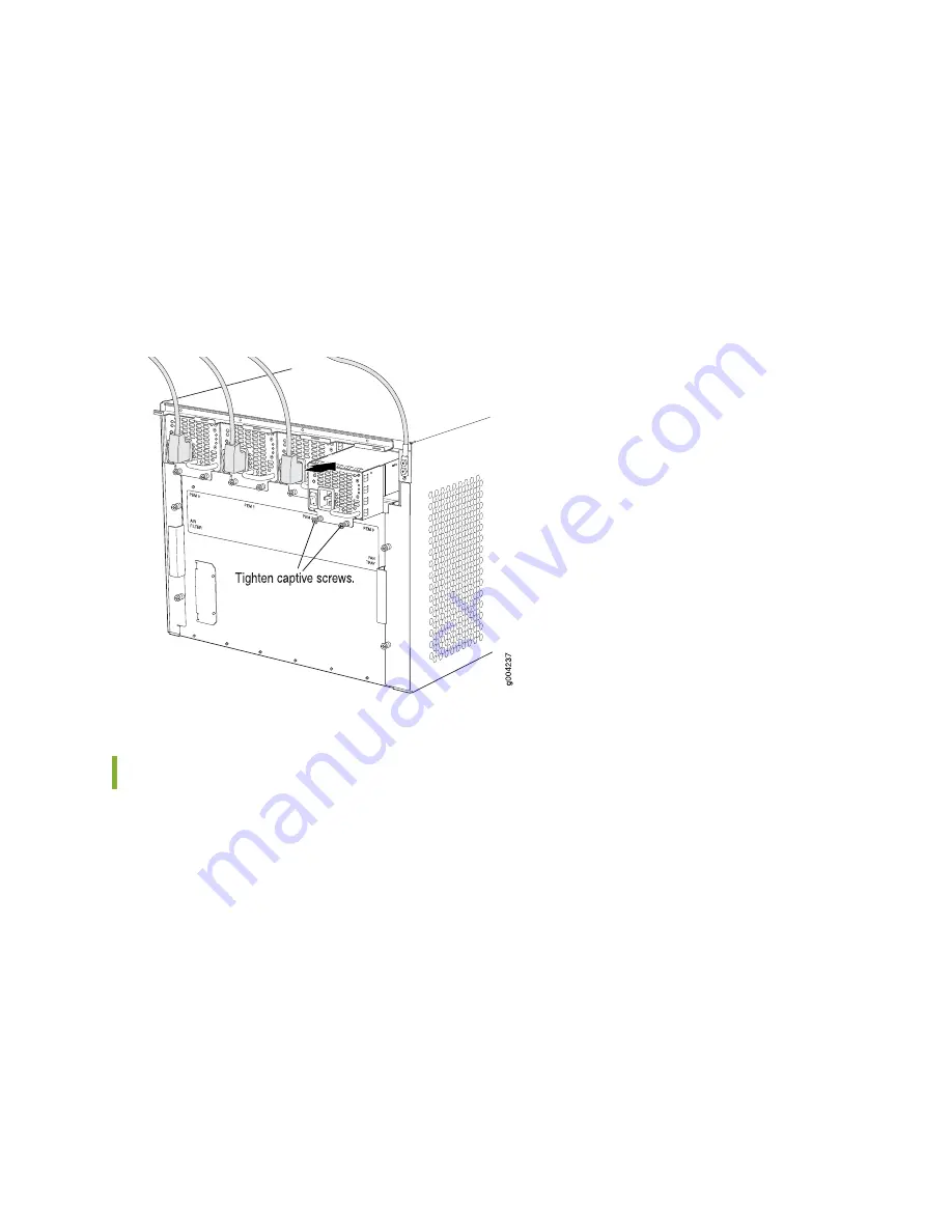
7. Attach the power cord to the AC power source, and switch on the dedicated facility circuit breaker for
the power supply. Follow the ESD and connection instructions for your site.
8. Move the AC switch next to the appliance inlet on the power supply to the on position ( | ) and observe
the status LEDs on the power supply faceplate. If the power supply is correctly installed and functioning
normally, the AC OK and DC OK LEDs light steadily, and the PS FAIL LED is not lit.
Figure 115: Installing an AC Power Supply
Replacing an SRX5600 Services Gateway AC Power Supply Cord
To replace an SRX5600 Services Gateway AC power supply cord, perform the following procedures:
1.
Disconnecting an SRX5600 Services Gateway AC Power Supply Cord | 258
2.
Connecting an SRX5600 Services Gateway AC Power Supply Cord | 258
257
Summary of Contents for SRX5600
Page 1: ...SRX5600 Services Gateway Hardware Guide Published 2020 02 14 ...
Page 23: ......
Page 105: ...LEDs 106 ...
Page 114: ...Figure 51 SRX5K MPC g030309 MPC empty 115 ...
Page 124: ...Port and Interface Numbering 125 ...
Page 130: ...Port and Interface Numbering 131 ...
Page 156: ......
Page 185: ......
Page 193: ...Figure 84 Installing the Front Mounting Hardware for a Four Post Rack or Cabinet 196 ...
Page 239: ......
Page 285: ...c Upload the configuration to RE2 from the USB device 288 ...
Page 372: ...5 CHAPTER Troubleshooting Hardware Troubleshooting the SRX5600 377 ...
Page 373: ......
Page 407: ......
Page 420: ...423 ...
Page 423: ...Restricted Access Area Warning 426 ...
Page 430: ...433 ...
Page 443: ...Jewelry Removal Warning 446 ...
Page 446: ...Operating Temperature Warning 449 ...
Page 456: ...DC Power Disconnection Warning 459 ...
Page 460: ...DC Power Wiring Sequence Warning 463 ...
Page 463: ...DC Power Wiring Terminations Warning 466 ...
Page 466: ...DC Power Disconnection Warning 469 ...
Page 470: ...DC Power Wiring Sequence Warning 473 ...


