The receiver uses the key ID and the sender’s address to determine the relevant
security association. The key ID is extracted from the received integrity object. The
address of the sending interface is extracted from the rsvp_hop object, if present,
or from the packet header if the message does not include the rsvp_hop object. The
receiver then recomputes the message digest using the association key and algorithm
and compares it to the digest received from the peer.
If the digests match, RSVP checks the received sequence number. Every message
received from a sender after the first authenticated message must have a sequence
number greater than the number from a previously authenticated message from that
sender. Messages with invalid sequence numbers are discarded.
If the sequence number is valid, then the RSVP message is authenticated and
forwarded for normal RSVP processing. Unauthenticated messages are discarded.
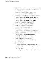
To configure RSVP-TE MD5 authentication:
1.
Assign a key to the interface for MD5 authentication between RSVP peers.
host1(config-if)#
mpls rsvp authentication key 34udR973j
2.
Enable MD5 authentication on the RSVP-TE interface.
host1(config-if)#
mpls rsvp authentication
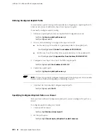
To clear the security association on a receiving peer for the specified sending peer:
■
Issue the
clear mpls rsvp authentication
command:
host1#
clear mpls rsvp authentication 10.3.5.1
Related Topics
■
Basic MPLS Configuration Tasks on page 268
■
Additional RSVP-TE Configuration Tasks on page 286
■
clear rsvp authentication
■
mpls rsvp authentication
■
mpls rsvp authentication key
Configuring RSVP-TE Fast Rerouting with RSVP-TE Bypass Tunnels
The fast reroute extensions to RSVP-TE enable you to create a single LSP, known as
a bypass tunnel, to back up a set of LSPs by bypassing specific links in the LSP. In
the event of a failure in any link of the protected RSVP-TE LSP (the primary LSP),
MPLS redirects traffic to the associated bypass tunnel in tens of milliseconds.
You must statically configure the bypass tunnel for each link that you want to protect
on each router in the LSP. The bypass tunnel must intersect the protected LSP at two
locations. The start of the bypass tunnels is the point of local repair (PLR), which is
the head end of the protected link. The bypass tunnel terminates downstream of the
PLR on the node that represents the end of the bypassed link on the primary LSP.
288
■
Configuring RSVP-TE Fast Rerouting with RSVP-TE Bypass Tunnels
JUNOSe 11.1.x BGP and MPLS Configuration Guide
Summary of Contents for BGP
Page 6: ...vi ...
Page 8: ...viii JUNOSe 11 1 x BGP and MPLS Configuration Guide ...
Page 37: ...Part 1 Border Gateway Protocol Configuring BGP Routing on page 3 Border Gateway Protocol 1 ...
Page 38: ...2 Border Gateway Protocol JUNOSe 11 1 x BGP and MPLS Configuration Guide ...
Page 234: ...198 Monitoring BGP JUNOSe 11 1 x BGP and MPLS Configuration Guide ...
Page 236: ...200 Multiprotocol Layer Switching JUNOSe 11 1 x BGP and MPLS Configuration Guide ...
Page 542: ...506 Monitoring BGP MPLS VPNs JUNOSe 11 1 x BGP and MPLS Configuration Guide ...
Page 544: ...508 Layer 2 Services Over MPLS JUNOSe 11 1 x BGP and MPLS Configuration Guide ...
Page 610: ...574 Virtual Private LAN Service JUNOSe 11 1 x BGP and MPLS Configuration Guide ...
Page 624: ...588 VPLS References JUNOSe 11 1 x BGP and MPLS Configuration Guide ...
Page 680: ...644 Virtual Private Wire Service JUNOSe 11 1 x BGP and MPLS Configuration Guide ...
Page 724: ...688 Monitoring MPLS Forwarding Table for VPWS JUNOSe 11 1 x BGP and MPLS Configuration Guide ...
Page 725: ...Part 6 Index Index on page 691 Index 689 ...
Page 726: ...690 Index JUNOSe 11 1 x BGP and MPLS Configuration Guide ...


