host2:pe2#
show ip bgp vpn all field in-label
Prefix In-label
10.12.0.0/16 none
10.24.0.0/16 16
On PE 1, you see that MP-BGP receives a labeled VPN-IPv4 prefix of 10.24.0.0/16
with an out label of 16. MP-BGP on PE 2 advertised this label with the prefix. In the
data plane, MPLS traffic is sent by PE 1 to PE 2 with this label.
host1:pe1#
show ip bgp vpn all field out-label
Prefix Out-label
10.12.0.0/16 none
10.24.0.0/16 16
On PE 2, you see that MP-BGP receives a labeled VPN-IPv4 prefix of 10.12.0.0/16
with an out label of 24. MP-BGP on PE 1 advertised this label with the prefix. In the
data plane, MPLS traffic is sent by PE 2 to PE 1 with this label.
host2:pe2#
show ip bgp vpn all field out-label
Prefix Out-label
10.12.0.0/16 24
10.24.0.0/16 none
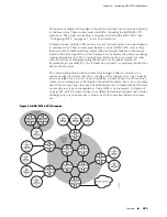
The data packets are transported within a VPN across the service provider core by
MPLS. This transport process requires two layers of MPLS labels, stacked one upon
the other.
The inner labels are assigned by each PE router for each VRF. When an MPLS packet
arrives at the egress PE router, that egress PE router uses the inner label to determine
which VRF the packet is destined for. In the default, per-VRF label allocation mode
(described in “Creating Labels per FEC” on page 438), the egress PE router does an
IP lookup in the IP forwarding table of that VRF using the IP destination address in
the IP packet that is encapsulated in the MPLS packet. The egress PE router then
forwards the IP packet (without the MPLS header) to the appropriate customer site.
The inner labels themselves are communicated between PE routers in the MP-BGP
extended update messages as described in the previous section.
MPLS uses the outer labels to forward data packets from the ingress PE router through
a succession of P routers across the core. This succession of P routers constitutes a
label-switched path (LSP), also referred to as an MPLS tunnel. The labels are assigned
to links in the path.
At each P router, MPLS pops the outer label from a data packet. The label is an index
into the P router’s forwarding table, from which it determines both the next hop
along the LSP and another label. The router pushes the label on to the label stack
and forwards the packet to the next P router. The combination of popping one label
and pushing another is known as a label swap. At the egress PE router, MPLS pops
the outer label, then the inner label. The inner label determines the CE router to
which the packet is sent. The P routers never examine the inner MPLS label or the
destination IP address encapsulated in the MPLS packet.
In many cases, the PE routers are fully meshed by means of LSPs. You can use tunnel
profiles to simplify the LSP configuration process. See “Configuring MPLS” on page 267,
for procedures to configure an LSP.
Transporting Packets Across an IP Backbone with MPLS
■
391
Chapter 5: Configuring BGP-MPLS Applications
Summary of Contents for BGP
Page 6: ...vi ...
Page 8: ...viii JUNOSe 11 1 x BGP and MPLS Configuration Guide ...
Page 37: ...Part 1 Border Gateway Protocol Configuring BGP Routing on page 3 Border Gateway Protocol 1 ...
Page 38: ...2 Border Gateway Protocol JUNOSe 11 1 x BGP and MPLS Configuration Guide ...
Page 234: ...198 Monitoring BGP JUNOSe 11 1 x BGP and MPLS Configuration Guide ...
Page 236: ...200 Multiprotocol Layer Switching JUNOSe 11 1 x BGP and MPLS Configuration Guide ...
Page 542: ...506 Monitoring BGP MPLS VPNs JUNOSe 11 1 x BGP and MPLS Configuration Guide ...
Page 544: ...508 Layer 2 Services Over MPLS JUNOSe 11 1 x BGP and MPLS Configuration Guide ...
Page 610: ...574 Virtual Private LAN Service JUNOSe 11 1 x BGP and MPLS Configuration Guide ...
Page 624: ...588 VPLS References JUNOSe 11 1 x BGP and MPLS Configuration Guide ...
Page 680: ...644 Virtual Private Wire Service JUNOSe 11 1 x BGP and MPLS Configuration Guide ...
Page 724: ...688 Monitoring MPLS Forwarding Table for VPWS JUNOSe 11 1 x BGP and MPLS Configuration Guide ...
Page 725: ...Part 6 Index Index on page 691 Index 689 ...
Page 726: ...690 Index JUNOSe 11 1 x BGP and MPLS Configuration Guide ...

