1.
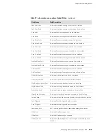
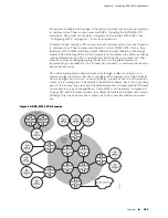
PE 1 sends an MPLS echo request UDP packet that contains an LDP IPv4 sub-TLV.
The packet is sent as a labeled packet over the target LSP. The packet has the
following attributes:
10.1.1.1
Source address
127.0.0.0/8
Destination address
3503
UDP port
255
TTL
10.2.2.2/32
IPv4 prefix in the TLV
Randomly generated 32-bit number used to match the reply
Sender’s handle
Integer that is incremented for each echo request packet
Sequence number
2.
Router P 1 label-switches the packet to P 2.
3.
Router P 2 label-switches the packet to PE 2 (assuming PHP is not configured).
4.
Router PE 2 pops the label and determines that the destination address is in the
127.0.0.0/8 subnet. PE 2 sends the packet up to the control plane. The MPLS
ping application on the control plane then creates an MPLS echo reply to the
received echo request. The echo reply packet has a return code of 3, which
means that the replying router is an egress for the FEC at stack depth. The echo
reply packet includes the Interface and Label Stack TLV to indicate both the
interface on which the request packet was received and the incoming label stack.
The MPLS echo reply packet is sent back as a (labeled) UDP packet with the
following attributes:
10.2.2.2
Source address
10.1.1.1
Destination address
3503
UDP port
5.
When the MPLS echo reply reaches router PE 1, the router matches the sender’s
handle and the sequence number to the echo request packet that PE 1 sent out.
If the values match, the CLI displays an exclamation point (!).
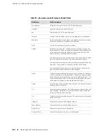
The following sample output represents what you might see when you issue the
ping
mpls ip
and
ping mpls ip detail
commands for the topology shown in Figure 67 on
page 370.
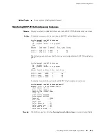
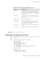
host1:pe1#
ping mpls ip 10.2.2.2/32
Sending 5 UDP echo requests for LDP IPv4 prefix, timeout = 2 sec
!!!!!
Success rate = 100% (5/5), round-trip min/avg/max = 4294967295/4/0 ms
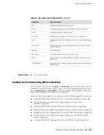
Packet Flow Examples for Verifying MPLS Connectivity
■
371
Chapter 4: Monitoring MPLS
Summary of Contents for BGP
Page 6: ...vi ...
Page 8: ...viii JUNOSe 11 1 x BGP and MPLS Configuration Guide ...
Page 37: ...Part 1 Border Gateway Protocol Configuring BGP Routing on page 3 Border Gateway Protocol 1 ...
Page 38: ...2 Border Gateway Protocol JUNOSe 11 1 x BGP and MPLS Configuration Guide ...
Page 234: ...198 Monitoring BGP JUNOSe 11 1 x BGP and MPLS Configuration Guide ...
Page 236: ...200 Multiprotocol Layer Switching JUNOSe 11 1 x BGP and MPLS Configuration Guide ...
Page 542: ...506 Monitoring BGP MPLS VPNs JUNOSe 11 1 x BGP and MPLS Configuration Guide ...
Page 544: ...508 Layer 2 Services Over MPLS JUNOSe 11 1 x BGP and MPLS Configuration Guide ...
Page 610: ...574 Virtual Private LAN Service JUNOSe 11 1 x BGP and MPLS Configuration Guide ...
Page 624: ...588 VPLS References JUNOSe 11 1 x BGP and MPLS Configuration Guide ...
Page 680: ...644 Virtual Private Wire Service JUNOSe 11 1 x BGP and MPLS Configuration Guide ...
Page 724: ...688 Monitoring MPLS Forwarding Table for VPWS JUNOSe 11 1 x BGP and MPLS Configuration Guide ...
Page 725: ...Part 6 Index Index on page 691 Index 689 ...
Page 726: ...690 Index JUNOSe 11 1 x BGP and MPLS Configuration Guide ...


