2.3 FUNCTIONS OF SOFTWARE BUTTONS
212
2
y
y
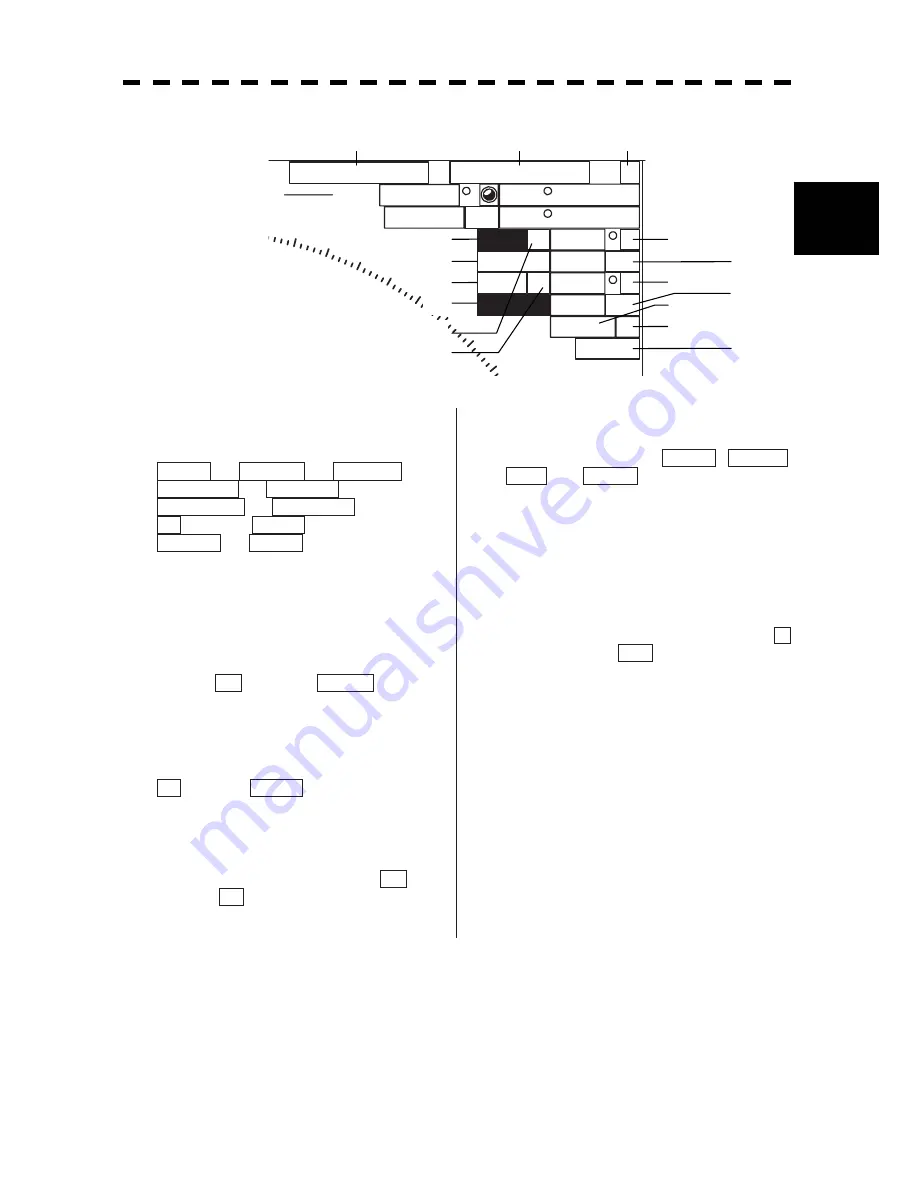
2.3.3 Software Buttons for Area 3 (Top-Right Corner of the Radar Display)
Cursor
(
Off
)
C
True
089.6
5.37 NM
35 33.037'
EBL1
T
VRM1
EBL2 T
VRM2
NM
NM
PC
CCRP1
N
140 01.597'E
10
020
030
040
050
045.0
3.00
135.0
6.00
C
Ԙ㧦
Cursor mode switching
The mode of the function that uses the cursor is
switched whenever this button is pressed.
AUTO
ACQ TT
ACT AIS
TGT DATA
CNCL TT
DEACT AIS
CNCL Data
(Mark)
-------- (Line)
Property
AUTO
ԙ㧦
Cursor mode: mark font / line
pattern switching
The currently selected cursor mode is indicated.
When the cursor is in the mark or line mode, use
this button to change the mark font pattern or line
pattern. If this button is clicked while the cursor
mode is (mark) or -------- (line), the
mark font / line pattern is changed.
Ԛ㧦
Mark color / line color switching
This function switches a mark color / line color. If
this button is clicked while the cursor mode is
(mark) or -------- (line), the mark color /
line color is changed.
ԛ㧦
Cursor bearing numeric value
display true / relative switching
The bearing numeric value display T (true
bearing) / R (relative bearing) of the cursor is
switched whenever this button is clicked.
ԜԝԞ
and
ԟ㧦
EBL1 / 2 and VRM1 /
2 adjustment
These functions set the EBL1 , VRM1 ,
EBL2 , and VRM2 displays to On / Off and
acquire the operation right.
If the button is clicked on, the operation right is
acquired. Make adjustments by moving the track
ball to the left and right Determine the
adjustment by pressing the
[ENT]
key.
Ԡ
and
ԡ㧦
EBL1, EBL2 numeric value
true / relative switching
The EBL1 / 2 bearing numeric value display T
(true bearing) / R (relative bearing) is
switched whenever the button is clicked.
If the button is clicked for 2 seconds, the EBL /
Cursor Setting menu is displayed.
ԛ
Ԙ
ԙ
Ԛ
Ԝ
ԝ
ԟ
Ԟ
Ԡ
ԡ
Ԣ
ԣ
ԥ
Ԥ
Ԧ
ԧ
Ԩ
Summary of Contents for JMA-5212-4
Page 2: ......
Page 18: ... xii NKE 2103 6 6HS Scanner Unit NKE 2254 7 9 6HS Scanner Unit Warning Label Warning Label ...
Page 19: ... xiii ...
Page 38: ... xxxii ...
Page 45: ...1 4 EXTERIOR DRAWINGS 1 6 1 y Fig 1 1 Exterior Drawing of Scanner Unit Type NKE 2103 4 ...
Page 46: ...1 7 Fig 1 2 Exterior Drawing of Scanner Unit Type NKE 2103 6 ...
Page 47: ...1 4 EXTERIOR DRAWINGS 1 8 1 y Fig 1 3 Exterior Drawing of Scanner Unit Type NKE 2254 7 ...
Page 48: ...1 9 Fig 1 4 Exterior Drawing of Scanner Unit Type NKE 2254 9 ...
Page 49: ...1 4 EXTERIOR DRAWINGS 1 10 1 y Fig 1 5 Exterior Drawing of Monitor Unit Type NWZ 164 ...
Page 50: ...1 11 Fig 1 6 Exterior Drawing of Processor Unit Type NDC 1460 ...
Page 51: ...1 4 EXTERIOR DRAWINGS 1 12 1 y Fig 1 7 Exterior Drawing of Keyboard Unit Type NCE 7699A ...
Page 52: ...1 13 Fig 1 8 Exterior Drawing of NSK Unit Type NCT 4106A ...
Page 56: ...1 17 ...
Page 58: ...2 1 2 1 EXAMPLE OF DISPLAY ...
Page 78: ...2 21 ...
Page 234: ...3 155 ...
Page 316: ...5 75 ...
Page 332: ...6 15 ...
Page 358: ...7 25 Exit 1 Press RADAR MENU key The Main Menu will reappear ...
Page 434: ...8 39 ...
Page 452: ...10 5 ...
Page 477: ...Figure 8 NKE 2254 Interconnection Diagram of Scanner Unit ...
Page 493: ......


