5.2 TT OPERATION
536
5
yy
yyy
[IV] Gate Display
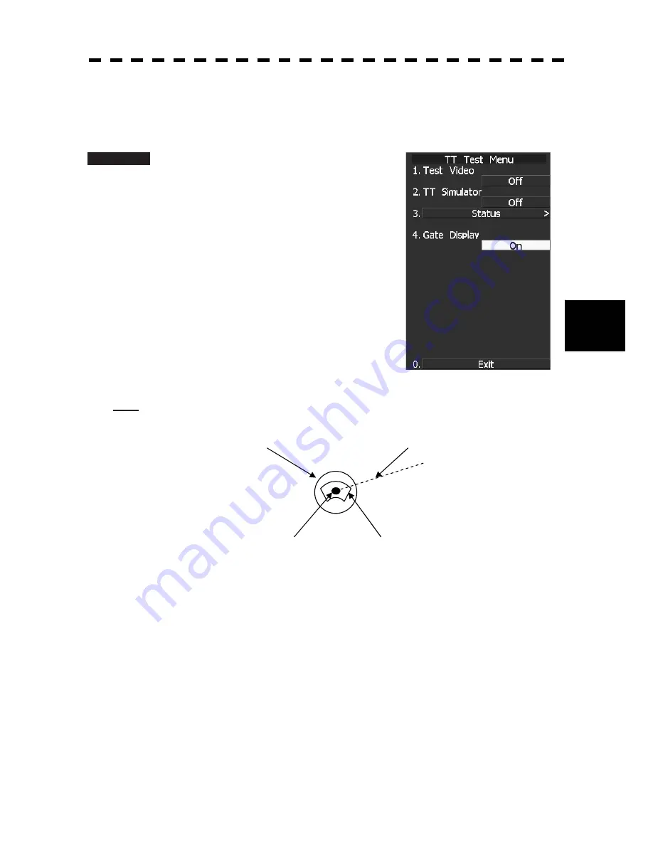
The gate displays an area monitoring a target using the TT function. This radar equipment allows the gate size
to change automatically according to target distance and size. User can check the gate size using the following
function.
Procedure
1 Press [TT MENU] key.
Press [6] key.
The TT Test Menu will appear.
2
Press [4] key.
The gate display mode is switched.
ON: Gate is displayed
OFF: Gate is not displayed
3
The gate displays data of a target you
want to check using the cursor and
[TGT DATA] key. (See Section 5.3.6
“Displaying Numeric Data of AIS
Targets (TGT DATA).”)
The data is displayed, and the gate is displayed
around the TT symbol in green.
Note:
The TT function can display the gate of two targets simultaneously.
TT symbol
Vector
Echo
Gate (displayed in green)
Summary of Contents for JMA-5212-4
Page 2: ......
Page 18: ... xii NKE 2103 6 6HS Scanner Unit NKE 2254 7 9 6HS Scanner Unit Warning Label Warning Label ...
Page 19: ... xiii ...
Page 38: ... xxxii ...
Page 45: ...1 4 EXTERIOR DRAWINGS 1 6 1 y Fig 1 1 Exterior Drawing of Scanner Unit Type NKE 2103 4 ...
Page 46: ...1 7 Fig 1 2 Exterior Drawing of Scanner Unit Type NKE 2103 6 ...
Page 47: ...1 4 EXTERIOR DRAWINGS 1 8 1 y Fig 1 3 Exterior Drawing of Scanner Unit Type NKE 2254 7 ...
Page 48: ...1 9 Fig 1 4 Exterior Drawing of Scanner Unit Type NKE 2254 9 ...
Page 49: ...1 4 EXTERIOR DRAWINGS 1 10 1 y Fig 1 5 Exterior Drawing of Monitor Unit Type NWZ 164 ...
Page 50: ...1 11 Fig 1 6 Exterior Drawing of Processor Unit Type NDC 1460 ...
Page 51: ...1 4 EXTERIOR DRAWINGS 1 12 1 y Fig 1 7 Exterior Drawing of Keyboard Unit Type NCE 7699A ...
Page 52: ...1 13 Fig 1 8 Exterior Drawing of NSK Unit Type NCT 4106A ...
Page 56: ...1 17 ...
Page 58: ...2 1 2 1 EXAMPLE OF DISPLAY ...
Page 78: ...2 21 ...
Page 234: ...3 155 ...
Page 316: ...5 75 ...
Page 332: ...6 15 ...
Page 358: ...7 25 Exit 1 Press RADAR MENU key The Main Menu will reappear ...
Page 434: ...8 39 ...
Page 452: ...10 5 ...
Page 477: ...Figure 8 NKE 2254 Interconnection Diagram of Scanner Unit ...
Page 493: ......


