2.3 FUNCTIONS OF SOFTWARE BUTTONS
220
2
y
y
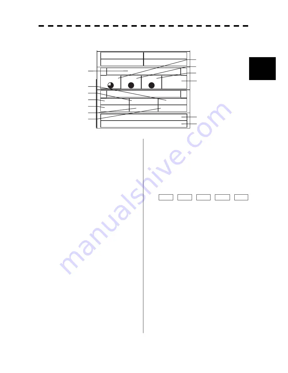
2.3.9 Software Buttons for Area 8 (Operation and Message Area)
(Right Side of the Radar Display)
Brilliance
<
>
Panel
VID
T T
Day1
Menu
<
>
RADAR
Close
T T
Map
Plot
Test
No Alarm
Ԙ㧦
Exit button
Click this button to exit the menu screen.
ԙ㧦
Main menu / Radar menu
Single-click this button to call up Main Menu.
Double-click this button to call up Radar Menu.
Ԛ㧦
TT menu (target menu)
Click this button to call up TT Menu.
ԛ㧦
Plotter menu
Click this button to call up Plot (Plotter) Menu.
Ԝ㧦
Map menu
Click this button to call up Map Setting.
ԝ㧦
Test menu
Click this button to call up Test Menu.
Ԟ㧦
Screen switch
Click this button to switch the screen between the
brilliance adjustment screen and the screen
information setting screen.
ԟ㧦
Panel brightness setting
Brightness of the operation panel can be changed.
Click this button to adjust brightness. It can be
set in 5 levels.
Ԡ㧦
Radar image brightness setting
Brightness of the radar image (echo) can be
adjusted.
Click this button to change brightness. It can be
set in 4 levels.
ԡ㧦
Tracked target / AIS target
brightness setting
Brightness of the tracked target / AIS target can be
adjusted.
Click this button to adjust brightness. It can be
set in 5 levels.
Ԣ㧦
Day/Night mode switch
Click this button to change the day/night mode in
the following order:
Day1
Ј
Day2
Ј
Dusk
Ј
Night
Ј
Day1
ԣ㧦
User map menu
Click this button to call up a menu screen for
loading a map created by a user.
Ԥ㧦
User setting menu
Click this button to call up a menu screen for
loading the user setting.
ԥ㧦
Alarm display
Click this button to stop the alarm buzzer and the
flashing of the alarm display.
When multiple alarms go off simultaneously, the
alarm that must be acknowledged first is
indicated.
The top line shows an alarm to be acknowledged
by clicking.
The bottom line shows the current alarms one by
one.
Ԧ㧦
Alarm indication
The system alarm indicated in red.
Other information indicated in blue or yellow.
Ԛ
ԙ
Ԙ
ԛ
Ԝ
ԝ
Ԡ
Ԣ
ԡ
ԟ
Ԟ
ԥ
Ԧ
Summary of Contents for JMA-5212-4
Page 2: ......
Page 18: ... xii NKE 2103 6 6HS Scanner Unit NKE 2254 7 9 6HS Scanner Unit Warning Label Warning Label ...
Page 19: ... xiii ...
Page 38: ... xxxii ...
Page 45: ...1 4 EXTERIOR DRAWINGS 1 6 1 y Fig 1 1 Exterior Drawing of Scanner Unit Type NKE 2103 4 ...
Page 46: ...1 7 Fig 1 2 Exterior Drawing of Scanner Unit Type NKE 2103 6 ...
Page 47: ...1 4 EXTERIOR DRAWINGS 1 8 1 y Fig 1 3 Exterior Drawing of Scanner Unit Type NKE 2254 7 ...
Page 48: ...1 9 Fig 1 4 Exterior Drawing of Scanner Unit Type NKE 2254 9 ...
Page 49: ...1 4 EXTERIOR DRAWINGS 1 10 1 y Fig 1 5 Exterior Drawing of Monitor Unit Type NWZ 164 ...
Page 50: ...1 11 Fig 1 6 Exterior Drawing of Processor Unit Type NDC 1460 ...
Page 51: ...1 4 EXTERIOR DRAWINGS 1 12 1 y Fig 1 7 Exterior Drawing of Keyboard Unit Type NCE 7699A ...
Page 52: ...1 13 Fig 1 8 Exterior Drawing of NSK Unit Type NCT 4106A ...
Page 56: ...1 17 ...
Page 58: ...2 1 2 1 EXAMPLE OF DISPLAY ...
Page 78: ...2 21 ...
Page 234: ...3 155 ...
Page 316: ...5 75 ...
Page 332: ...6 15 ...
Page 358: ...7 25 Exit 1 Press RADAR MENU key The Main Menu will reappear ...
Page 434: ...8 39 ...
Page 452: ...10 5 ...
Page 477: ...Figure 8 NKE 2254 Interconnection Diagram of Scanner Unit ...
Page 493: ......


