


33
GEN04
Chapter 9 - High-Level System Troubleshooting
Note: As the hand piece ages, the generator performs
measurements and updates a key hand piece parameter. This
function is performed when the internal temperature of the hand
piece is stable at room temperature. Certain usage patterns may
prevent this update from occurring and subsequently make the
hand piece diagnostics more sensitive to temperature. The steps
above will cause an update of the hand piece parameter and
return the system to designed sensitivity.
Warning:
To avoid user or patient injury, ensure that the
instrument is clear of other instruments, drapes, the patient or
other objects before pressing TEST. Safety measures (in
accordance with hospital protocol) taken in the presence of
aerosols should be in effect while in Test mode.
Note: Do not run the Test mode while an electrosurgical
generator is being activated in the room. Interference from the
electrosurgical generator may affect test results.
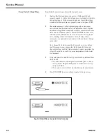
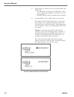
Fig. 9-4 Hand Piece Over-Temperature Error Screens
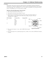
Error Code 5: Instrument
Error Code 5 indicates a problem with the instrument.
1
The instrument may not be tightened properly or tissue may have
collected in the distal end of the instrument shaft. Tighten
instrument using blade wrench and carefully remove tissue from
distal end of instrument sheath. Press STANDBY to clear error
code and return to Ready mode. Activate system. If the pre-run
test is running, ensure instrument is in air. If using shears, ensure
jaws are open and not in contact with any objects during pre-run
test.
Note: Inspect the blade wrench hub for cracks or wear before
use. If damage is seen, replace the blade wrench. Before use
after autoclaving, cool the blade wrench at room temperature for
at least 45 minutes or soak it in room temperature sterile water
for 5 minutes.
Summary of Contents for ETHICON ENDO-SURGERY HARMONIC 300
Page 1: ...HARMONIC Generator 300 System Service Manual ...
Page 2: ...GEN04 ...
Page 6: ...4 GEN04 Service Manual ...
Page 10: ...8 GEN04 Service Manual ...
Page 16: ...14 GEN04 Service Manual ...
Page 24: ...22 GEN04 Service Manual ...
Page 26: ...24 GEN04 Service Manual ...
Page 28: ...26 GEN04 Service Manual ...
Page 44: ...42 GEN04 Service Manual ...
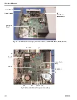
Page 50: ...48 GEN04 Service Manual Power Supply Fig 12 5 Power Supply Troubleshooting Flowchart ...
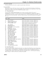
Page 52: ...50 GEN04 Service Manual Front Bezel Fig 12 7 Front Bezel Troubleshooting Flowchart ...
Page 58: ...56 GEN04 Service Manual ...
Page 62: ...60 GEN04 Service Manual ...
Page 66: ...64 GEN04 Service Manual ...
Page 68: ...66 GEN04 Service Manual ...
Page 72: ...70 GEN04 Service Manual ...
Page 76: ...74 GEN04 Service Manual ...
Page 77: ...75 GEN04 Appendix B GEN04 Main Assembly Drawing ...
Page 79: ...77 GEN04 Appendix C GEN04 Top Level Diagram Hand Piece ID Hand Piece Transducer ...


