


16
GEN04
Service Manual
9
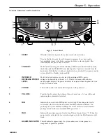
HAND PIECE
This receptacle is used to connect the hand piece to the generator.
RECEPTACLE
10
HAND ACTIVATION
When the indicator is green, hand activation on the hand switching adaptor is
enabled. To disable the Hand Activation mode, depress the button. Upon power-up,
the system defaults to Hand Activation mode disabled.
Note: If the foot switch is installed, the foot switch is always enabled.
11
TEST
Depressing this button initiates the Test mode. This mode is used during
troubleshooting. The generator will emit a tone when the Test mode is active and
“TEST IN PROGRESS” will appear on the display.
12
GRAPHIC DISPLAY
In Ready or Standby modes, this display indicates the minimum (user-settable
level 1 to 5) and maximum (level 5) power levels. If a system or component
problem exists, error codes will appear on this display.
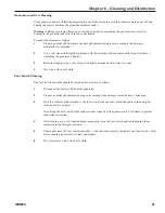
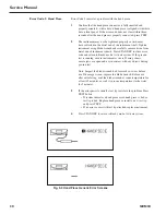
Fig. 5-2 Back Panel
13
FOOT SWITCH
Identical receptacles allow connection of up to two foot switch
RECEPTACLES
assemblies for user convenience. If only one foot switch is used, connect to either
receptacle.
14
POTENTIAL
This terminal provides a means for connection to a Potential Equalization
EQUALIZATION
Conductor.
TERMINAL
15
FUSES
Refer to the Replacement Parts drawings in the back of this manual for additional
fuse locations and fuse type.
16
POWER CORD
This receptacle is used to attach the power cord to the generator. For
RECEPTACLE
power cord requirements, refer to Chapter 14 – System Specifications.
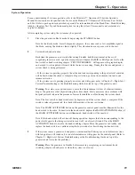
AUDIBLE SIGNALS
The generator delivers audible tones to signal activation, test, and alarm states. The
user may choose from three activation tone pitches. Refer to
Chapter 15 – Adjustments for tone selection information. Upon power-up, the
system defaults to the last tone chosen (the mid-pitch tone is factory-set).
T3.15H 250V
13
14
15
16
Summary of Contents for ETHICON ENDO-SURGERY HARMONIC 300
Page 1: ...HARMONIC Generator 300 System Service Manual ...
Page 2: ...GEN04 ...
Page 6: ...4 GEN04 Service Manual ...
Page 10: ...8 GEN04 Service Manual ...
Page 16: ...14 GEN04 Service Manual ...
Page 24: ...22 GEN04 Service Manual ...
Page 26: ...24 GEN04 Service Manual ...
Page 28: ...26 GEN04 Service Manual ...
Page 44: ...42 GEN04 Service Manual ...
Page 50: ...48 GEN04 Service Manual Power Supply Fig 12 5 Power Supply Troubleshooting Flowchart ...
Page 52: ...50 GEN04 Service Manual Front Bezel Fig 12 7 Front Bezel Troubleshooting Flowchart ...
Page 58: ...56 GEN04 Service Manual ...
Page 62: ...60 GEN04 Service Manual ...
Page 66: ...64 GEN04 Service Manual ...
Page 68: ...66 GEN04 Service Manual ...
Page 72: ...70 GEN04 Service Manual ...
Page 76: ...74 GEN04 Service Manual ...
Page 77: ...75 GEN04 Appendix B GEN04 Main Assembly Drawing ...
Page 79: ...77 GEN04 Appendix C GEN04 Top Level Diagram Hand Piece ID Hand Piece Transducer ...


