


25
GEN04
Chapter 8 - Generator Output Check
Procedure for Checking the output of GEN300 Generators
1
Perform the functional test sequence of steps contained in the service manual, Chapter 7 – Safety
and Function Testing (page 23).
2
Then check the generator’s current output:
a
.
Power the generator off. Wait 10 seconds.
b
.
Power the generator on while firmly pressing both “
Standby
” and “
Min Power-down
”
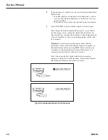
buttons simultaneously. Continuously press the two buttons until page number 1 of the
BME display mode is visible and only the Standby indicator is lit.
Note: A Generator “
Error Code #1
” will result if the two buttons are not continuously
pressed as described and the generator will have to be powered down and back up again.
c
.
Connect a known good HP054 Hand Piece to the generator.
Note: Make sure the hand piece is not hot (i.e., at room temperature).
d
.
Using the torque wrench for the hand piece, attach the test tip to the hand piece.
e
.
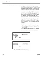
Use the up and down arrows to scroll to page 2.
f
.
Record
the current set point value for the hand piece listed on page 2.
Expected Output Current = _____________________________
g
.
Press the “
Standby
” key to enter Ready state.
h
.
Activate at level 5 by pressing the max foot switch pedal or max switch on the hand
switching adapter while keeping the test tip in air.
i
.
Allow the pre-run test to complete. Terminate activation after regular max activation beeps
are audible.
j
.
Record
the current on the display while continuing to activate at level 5.
Actual Current Output = _______________________________
k
.
Note: The current read should be within
+/- 1%
of the current recorded on page 2 of the
standby screen’s display.
If further confirmation of output is desired, remove the box cover and measure the current in
step f with a true RMS Digital Volt Meter with a bandwidth of at least 300Khz .
Make the voltage measurement across the series combination of R233 & R234
Note: for ease of testing and best accuracy, clip one test lead on the leg of R229 closest to
R233 and hold the other test lead on the leg of R234 that is furthest away from R229.
Note: Since the resistance value of the series combination of R233&R234 is 1ohm, the
voltage read in mV RMS is equal to the current in mA RMS.
3
If the GEN300 passes the above steps, then generator current output is functioning properly.
Summary of Contents for ETHICON ENDO-SURGERY HARMONIC 300
Page 1: ...HARMONIC Generator 300 System Service Manual ...
Page 2: ...GEN04 ...
Page 6: ...4 GEN04 Service Manual ...
Page 10: ...8 GEN04 Service Manual ...
Page 16: ...14 GEN04 Service Manual ...
Page 24: ...22 GEN04 Service Manual ...
Page 26: ...24 GEN04 Service Manual ...
Page 28: ...26 GEN04 Service Manual ...
Page 44: ...42 GEN04 Service Manual ...
Page 50: ...48 GEN04 Service Manual Power Supply Fig 12 5 Power Supply Troubleshooting Flowchart ...
Page 52: ...50 GEN04 Service Manual Front Bezel Fig 12 7 Front Bezel Troubleshooting Flowchart ...
Page 58: ...56 GEN04 Service Manual ...
Page 62: ...60 GEN04 Service Manual ...
Page 66: ...64 GEN04 Service Manual ...
Page 68: ...66 GEN04 Service Manual ...
Page 72: ...70 GEN04 Service Manual ...
Page 76: ...74 GEN04 Service Manual ...
Page 77: ...75 GEN04 Appendix B GEN04 Main Assembly Drawing ...
Page 79: ...77 GEN04 Appendix C GEN04 Top Level Diagram Hand Piece ID Hand Piece Transducer ...


