


17
GEN04
Chapter 5 - Operation
Screen Descriptions
Power-Up Screen
Below is an
example
of the Software Version displayed during power-up.
Fig. 5-3 Power-Up Screen
Tone Selection Screen
Refer to Chapter 15 – Adjustments for descriptions of the Tone Selection Screens.
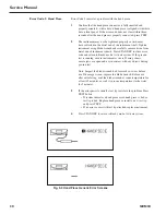
User-Initiated and Pre-Activation Test Screens
The generator will cycle between the following two screens, displaying each screen briefly, for the duration
of the time that the system is in the User-Initiated Test state and Pre-Activation Test state. Refer to
Chapter 7 – Safety and Function Testing for details.
Fig. 5-4 Test in Progress Screens
Standby, Ready and Run Screens
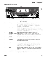
The Standby, Ready, and Run screen appearances depend on the mode in which the system is running. In
Normal mode, the Standby, Ready, and Run screens are the same and indicate the MAX power level of 5 on
the right, and the user selected MIN power level on the left (1 to 5). In Developer/Biomed mode, the Standby
screen indicates the user selected MIN power level on the left, and a subset of system parameters on the right.
In Developer/Biomed mode, the Ready screen displays the user selected MIN Power level on the left (1 to 5)
and the system run time parameters on the right. Developer/Biomed Run screen is identical to the
Developer/Biomed Ready screen.
Summary of Contents for ETHICON ENDO-SURGERY HARMONIC 300
Page 1: ...HARMONIC Generator 300 System Service Manual ...
Page 2: ...GEN04 ...
Page 6: ...4 GEN04 Service Manual ...
Page 10: ...8 GEN04 Service Manual ...
Page 16: ...14 GEN04 Service Manual ...
Page 24: ...22 GEN04 Service Manual ...
Page 26: ...24 GEN04 Service Manual ...
Page 28: ...26 GEN04 Service Manual ...
Page 44: ...42 GEN04 Service Manual ...
Page 50: ...48 GEN04 Service Manual Power Supply Fig 12 5 Power Supply Troubleshooting Flowchart ...
Page 52: ...50 GEN04 Service Manual Front Bezel Fig 12 7 Front Bezel Troubleshooting Flowchart ...
Page 58: ...56 GEN04 Service Manual ...
Page 62: ...60 GEN04 Service Manual ...
Page 66: ...64 GEN04 Service Manual ...
Page 68: ...66 GEN04 Service Manual ...
Page 72: ...70 GEN04 Service Manual ...
Page 76: ...74 GEN04 Service Manual ...
Page 77: ...75 GEN04 Appendix B GEN04 Main Assembly Drawing ...
Page 79: ...77 GEN04 Appendix C GEN04 Top Level Diagram Hand Piece ID Hand Piece Transducer ...


