


19
GEN04
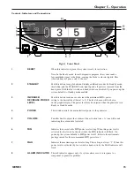
Chapter 5 - Operation
System Operation
For an understanding of system operation, refer to the H
ARMONIC
™ Generator 300 System Operator’s
Manual for instructions and specifications for use of the H
ARMONIC
™ Generator 300 System, Foot Switch,
and Cart. Refer to package inserts provided separately for information about the Hand Piece, Hand Switching
Adaptor, Adaptors, Test Tip and Instruments prior to using the system. This manual is not a reference to
surgical techniques.
After completing system setup, the system may be operated.
1
Place the generator in Ready mode by depressing the STANDBY button.
Note: In the Ready mode, for self-diagnostic purposes, the system sends a low-amplitude signal to
the blade, causing the blade to vibrate slightly. This vibration does not pose a risk to the user.
2
System check and activation:
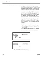
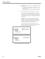
Each time the generator is activated after exiting Standby, hold the instrument in the air (if
coagulating shears are used, open the clamp arm) and depress the MIN or MAX power level on the
foot switch or hand switching adaptor. “TEST IN PROGRESS” will appear on the graphic display
and a rapid two-tone pulse will sound while the test is occurring. During this five-second period, a
system check is being performed.
• If the system is operating properly, the activation tone corresponding to the power level activated
will be heard when the check is complete. Stop activation, position the instrument on tissue, and
resume activation.
• If the system is not operating properly, an error code will appear (refer to Chapter 9 – High-Level
System Troubleshooting or the Troubleshooting Guide located on top of the generator unit).
Warning:
To avoid user or patient injury, ensure that the instrument is clear of other instruments,
drapes, the patient or other objects during the system check. Safety measures (in accordance with
hospital protocol) taken in the presence of aerosols should be in effect during the system check.
Note: The foot switch or hand switch must be depressed until the system check is complete. If the
switch is released prematurely, the check will reinitiate at the next activation.
Note: The HAND ACTIVATION button on the generator control panel must be illuminated for the
hand switch to be active. To deactivate the hand switch, depress the HAND ACTIVATION button (if
the HAND ACTIVATION button is not illuminated, hand switch will be inactive).
Note: If the hand switch will not turn off during operation, depress the button corresponding to the
power level opposite that being activated to turn it off - an alarm will sound. Press the HAND
ACTIVATION button to disable the hand switching adaptor. Place the generator in Standby, and
replace the hand switch; or, continue using the foot switch after deactivating the hand switch.
3
If the system senses a generator, hand piece, or instrument fault during use, an audible alarm (tone
with long pulses) will sound and a visual alarm indicator will appear on the control panel. (Refer to
Chapter 9 – High-Level System Troubleshooting or the Troubleshooting Guide on top of the
generator unit to resolve the problem.)
Warning:
Place the generator in Standby before removing or replacing an instrument, hand
switching adaptor or hand piece or when the system is not in use.
Summary of Contents for ETHICON ENDO-SURGERY HARMONIC 300
Page 1: ...HARMONIC Generator 300 System Service Manual ...
Page 2: ...GEN04 ...
Page 6: ...4 GEN04 Service Manual ...
Page 10: ...8 GEN04 Service Manual ...
Page 16: ...14 GEN04 Service Manual ...
Page 24: ...22 GEN04 Service Manual ...
Page 26: ...24 GEN04 Service Manual ...
Page 28: ...26 GEN04 Service Manual ...
Page 44: ...42 GEN04 Service Manual ...
Page 50: ...48 GEN04 Service Manual Power Supply Fig 12 5 Power Supply Troubleshooting Flowchart ...
Page 52: ...50 GEN04 Service Manual Front Bezel Fig 12 7 Front Bezel Troubleshooting Flowchart ...
Page 58: ...56 GEN04 Service Manual ...
Page 62: ...60 GEN04 Service Manual ...
Page 66: ...64 GEN04 Service Manual ...
Page 68: ...66 GEN04 Service Manual ...
Page 72: ...70 GEN04 Service Manual ...
Page 76: ...74 GEN04 Service Manual ...
Page 77: ...75 GEN04 Appendix B GEN04 Main Assembly Drawing ...
Page 79: ...77 GEN04 Appendix C GEN04 Top Level Diagram Hand Piece ID Hand Piece Transducer ...


