SECTION 3 - CHASSIS & TURNTABLE
3-48
– JLG Lift –
3121290
2.
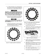
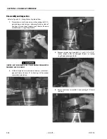
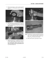
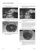
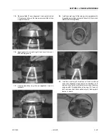
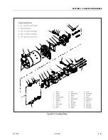
Remove rotor set (8) and wearplate (9), together to hold
rotor set in its assembled form, keeping same rotor vane
to stator contact surfaces. Drive link (10) may come away
from coupling shaft (12) with rotor set and wearplate.
Shift rotor set on wearplate and remove drive link if
needed. Inspect assembled rotor set for nicks, scoring,
or spalling on any surface, and for broken or worn
splines. If a rotor set component requires replacement,
complete rotor set must be replaced as it is a matched
set. Inspect wearplate for cracks, brinelling, or scoring.
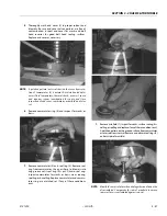
3.
Discard seal ring (4) between rotor set and wearplate.
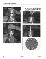
NOTE:
Rotor set (8) components may become disassembled dur-
ing service. Mark surface of rotor and stator facing UP, with
etching ink or grease pencil before removal to ensure cor-
rect reassembly of rotor into stator and rotor set into
motor. Mark all rotor components and mating spline com-
ponents for exact repositioning at assembly for maximum
wear life and performance of rotor set and motor.
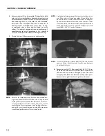
NOTE:
A polished pattern on wear plate from rotor rotation is nor-
mal. Place rotor set (8) and wear plate (9) on a flat surface
and center rotor in stator so two rotor lobes (180 degrees
apart) and a roller vane centerline are on the same stator
centerline. Check rotor lobe to roller vane clearance with a
feeler gage at this common centerline. Replace rotor set If
more than 0.005" (0.13 mm) of clearance.
NOTE:
If rotor set (8) has two stator halves and two sets of seven
vanes as shown, check rotor lobe to roller vane clearance
at both ends of rotor.
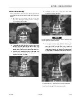
4.
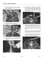
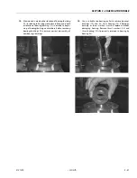
Remove drive link (10) from coupling shaft (12) if it was
not removed with rotor set and wear plate. Inspect drive
link for cracks and worn or damaged splines. No visible
lash (play) should be seen between mating spline parts.
Remove seal ring (4) from housing (18) and discard.
Summary of Contents for 450A II Series
Page 46: ...SECTION 3 CHASSIS TURNTABLE 3 6 JLG Lift 3121290 Figure 3 4 Drive Hub 4WD Front Only ...
Page 79: ...SECTION 3 CHASSIS TURNTABLE 3121290 JLG Lift 3 39 Figure 3 32 Swing Bearing Drive ...
Page 101: ...SECTION 3 CHASSIS TURNTABLE 3121290 JLG Lift 3 61 Figure 3 42 Auxiliary Pump ...
Page 113: ...SECTION 3 CHASSIS TURNTABLE 3121290 JLG Lift 3 73 Figure 3 53 EMR2 Fault Codes Sheet 1 of 5 ...
Page 114: ...SECTION 3 CHASSIS TURNTABLE 3 74 JLG Lift 3121290 Figure 3 54 EMR2 Fault Codes Sheet 2 of 5 ...
Page 115: ...SECTION 3 CHASSIS TURNTABLE 3121290 JLG Lift 3 75 Figure 3 55 EMR2 Fault Codes Sheet 3 of 5 ...
Page 116: ...SECTION 3 CHASSIS TURNTABLE 3 76 JLG Lift 3121290 Figure 3 56 EMR2 Fault Codes Sheet 4 of 5 ...
Page 117: ...SECTION 3 CHASSIS TURNTABLE 3121290 JLG Lift 3 77 Figure 3 57 EMR2 Fault Codes Sheet 5 of 5 ...
Page 159: ...SECTION 3 CHASSIS TURNTABLE 3121290 JLG Lift 3 119 ...
Page 161: ...SECTION 3 CHASSIS TURNTABLE 3121290 JLG Lift 3 121 ...
Page 163: ...SECTION 3 CHASSIS TURNTABLE 3121290 JLG Lift 3 123 ...
Page 165: ...SECTION 3 CHASSIS TURNTABLE 3121290 JLG Lift 3 125 ...
Page 173: ...SECTION 3 CHASSIS TURNTABLE 3121290 JLG Lift 3 133 Sensor Transducer Type ...
Page 177: ...SECTION 3 CHASSIS TURNTABLE 3121290 JLG Lift 3 137 Sensor Transducer Type ...
Page 179: ...SECTION 3 CHASSIS TURNTABLE 3121290 JLG Lift 3 139 ...
Page 181: ...SECTION 3 CHASSIS TURNTABLE 3121290 JLG Lift 3 141 ...
Page 183: ...SECTION 3 CHASSIS TURNTABLE 3121290 JLG Lift 3 143 ...
Page 185: ...SECTION 3 CHASSIS TURNTABLE 3121290 JLG Lift 3 145 ...
Page 187: ...SECTION 3 CHASSIS TURNTABLE 3121290 JLG Lift 3 147 ...
Page 203: ...SECTION 3 CHASSIS TURNTABLE 3121290 JLG Lift 3 163 ...
Page 207: ...SECTION 3 CHASSIS TURNTABLE 3121290 JLG Lift 3 167 ...
Page 217: ...SECTION 4 BOOM PLATFORM 3121290 JLG Lift 4 5 Figure 4 2 Boom Limit Switches ...
Page 310: ...SECTION 5 HYDRAULICS 5 70 JLG Lift 3121290 NOTES ...
Page 312: ...SECTION 6 JLG CONTROL SYSTEM 6 2 JLG Lift 3121290 Figure 6 2 Controller Block Diagram 0 ...
Page 370: ...SECTION 6 JLG CONTROL SYSTEM 6 60 JLG Lift 3121290 NOTES ...
Page 394: ...SECTION 7 BASIC ELECTRICAL INFORMATION SCHEMATICS 7 24 JLG Lift 3121290 NOTES ...
Page 395: ......


