


SECTION 7 - BASIC ELECTRICAL INFORMATION & SCHEMATICS
3121290
– JLG Lift –
7-3
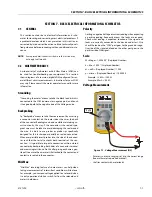
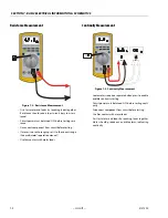
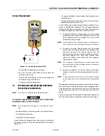
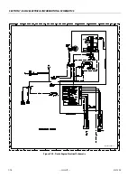
Current Measurement
• Set up meter for expected current range
• Be sure to connect meter leads to correct jacks for
selected current range
• If meter is not auto ranging, set it to correct range (See
multi meter’s operation manual)
• Use firm contact with meter leads
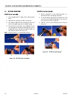
7.3
APPLYING SILICONE DIELECTRIC COMPOUND
TO ELECTRICAL CONNECTIONS
NOTE:
This section is not applicable for battery terminals.
JLG P/N 0100048 DIELECTRIC GREASE (NOVAGARD G661) IS THE ONLY MATE-
RIAL APPROVED FOR USE AS A DIELECTRIC GREASE.
NOTE:
Do NOT apply dielectric grease to the following connec-
tions:
• Main Boom Rotary sensor connections (on Celesco Sensor),
• LSS Modules connections,
• Deutz EMR 2 ECM connection.
Silicone Dielectric Compound must be used on all electrical
connections except for those mentioned above for the follow-
ing reasons:
• To prevent oxidation at mechanical joint between male
and female pins.
• To prevent electrical malfunction caused by low level con-
ductivity between pins when wet.
Use the following procedure to apply Silicone Dielectric Com-
pound to the electrical connectors. This procedure applies to
all plug connections not enclosed in a box. Silicone grease
should not be applied to connectors with external seals.
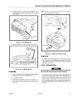
1.
To prevent oxidation, silicone grease must be packed
completely around male and female pins on the inside
of the connector prior to assembly. This is most easily
achieved by using a syringe.
NOTE:
Over a period of time, oxidation increases electrical resis-
tance at the connection, eventually causing circuit failure.
2.
To prevent shorting, silicone grease must be packed
around each wire where they enter the outside of the
connector housing. Also, silicone grease must be
applied at the joint where the male and female connec-
tors come together. Any other joints (around strain
reliefs, etc.) where water could enter the connector
should also be sealed.
NOTE:
This condition is especially common when machines are
pressure washed since the washing solution is much more
conductive than water.
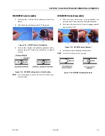
3.
Anderson connectors for battery boxes and battery
chargers should have silicone grease applied to contacts
only.
NOTE:
Curing-type sealants can also be used to prevent shorting
and would be less messy, but make future pin removal diffi-
cult.
When applied to electrical connections, dielectric grease helps
prevent corrosion of electrical contacts and improper conduc-
tivity between contacts from moisture intrusion. Open and
sealed connectors benefit from application of dielectric
grease.
Dielectric grease shall be applied to all electrical connectors at
the time of connection (except those noted under Exclusions).
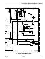
Figure 7-4. Current Measurement (DC)
Summary of Contents for 450A II Series
Page 46: ...SECTION 3 CHASSIS TURNTABLE 3 6 JLG Lift 3121290 Figure 3 4 Drive Hub 4WD Front Only ...
Page 79: ...SECTION 3 CHASSIS TURNTABLE 3121290 JLG Lift 3 39 Figure 3 32 Swing Bearing Drive ...
Page 101: ...SECTION 3 CHASSIS TURNTABLE 3121290 JLG Lift 3 61 Figure 3 42 Auxiliary Pump ...
Page 113: ...SECTION 3 CHASSIS TURNTABLE 3121290 JLG Lift 3 73 Figure 3 53 EMR2 Fault Codes Sheet 1 of 5 ...
Page 114: ...SECTION 3 CHASSIS TURNTABLE 3 74 JLG Lift 3121290 Figure 3 54 EMR2 Fault Codes Sheet 2 of 5 ...
Page 115: ...SECTION 3 CHASSIS TURNTABLE 3121290 JLG Lift 3 75 Figure 3 55 EMR2 Fault Codes Sheet 3 of 5 ...
Page 116: ...SECTION 3 CHASSIS TURNTABLE 3 76 JLG Lift 3121290 Figure 3 56 EMR2 Fault Codes Sheet 4 of 5 ...
Page 117: ...SECTION 3 CHASSIS TURNTABLE 3121290 JLG Lift 3 77 Figure 3 57 EMR2 Fault Codes Sheet 5 of 5 ...
Page 159: ...SECTION 3 CHASSIS TURNTABLE 3121290 JLG Lift 3 119 ...
Page 161: ...SECTION 3 CHASSIS TURNTABLE 3121290 JLG Lift 3 121 ...
Page 163: ...SECTION 3 CHASSIS TURNTABLE 3121290 JLG Lift 3 123 ...
Page 165: ...SECTION 3 CHASSIS TURNTABLE 3121290 JLG Lift 3 125 ...
Page 173: ...SECTION 3 CHASSIS TURNTABLE 3121290 JLG Lift 3 133 Sensor Transducer Type ...
Page 177: ...SECTION 3 CHASSIS TURNTABLE 3121290 JLG Lift 3 137 Sensor Transducer Type ...
Page 179: ...SECTION 3 CHASSIS TURNTABLE 3121290 JLG Lift 3 139 ...
Page 181: ...SECTION 3 CHASSIS TURNTABLE 3121290 JLG Lift 3 141 ...
Page 183: ...SECTION 3 CHASSIS TURNTABLE 3121290 JLG Lift 3 143 ...
Page 185: ...SECTION 3 CHASSIS TURNTABLE 3121290 JLG Lift 3 145 ...
Page 187: ...SECTION 3 CHASSIS TURNTABLE 3121290 JLG Lift 3 147 ...
Page 203: ...SECTION 3 CHASSIS TURNTABLE 3121290 JLG Lift 3 163 ...
Page 207: ...SECTION 3 CHASSIS TURNTABLE 3121290 JLG Lift 3 167 ...
Page 217: ...SECTION 4 BOOM PLATFORM 3121290 JLG Lift 4 5 Figure 4 2 Boom Limit Switches ...
Page 310: ...SECTION 5 HYDRAULICS 5 70 JLG Lift 3121290 NOTES ...
Page 312: ...SECTION 6 JLG CONTROL SYSTEM 6 2 JLG Lift 3121290 Figure 6 2 Controller Block Diagram 0 ...
Page 370: ...SECTION 6 JLG CONTROL SYSTEM 6 60 JLG Lift 3121290 NOTES ...
Page 394: ...SECTION 7 BASIC ELECTRICAL INFORMATION SCHEMATICS 7 24 JLG Lift 3121290 NOTES ...
Page 395: ......


