


SECTION 3 - CHASSIS & TURNTABLE
3121290
– JLG Lift –
3-87
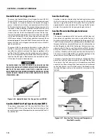
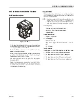
Fuel Filter
After fuel is drawn into the fuel pump, the fuel flows through
the gasoline fuel filter. The fuel filter traps small particles as
fuel passes through the filter to remove debris and prevents
fuel pressure and temperature manifold and fuel injectors
from becoming damaged. Fuel filter maintenance is required
as shown in Section 1.
Fuel Injector Rail
Fuel flows from the fuel pressure and temperature manifold
assembly to the fuel rails where fuel is delivered to the fuel
injectors. The fuel rail also contains a Schrader valve which is
used to test regulated pressure of the fuel system.
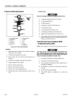
Fuel Injector
The fuel supply is maintained on the top of the injector from
the injector rail. The injector is fed a "pulse" signal through the
wire harness which causes the injector to open. During regular
operating conditions the ECM controls the opening and dura-
tion of opening of the injector. During lower RPM operation
the injector signals or "pulses" are less frequent then when the
engine is operating at higher RPMs. The engine has been cali-
brated to deliver the precise amount of fuel for optimum per-
formance and emission control.
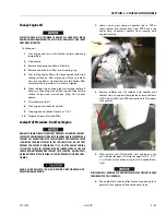
3.15 GM ENGINE FUEL SYSTEM REPAIR
Propane Fuel System Pressure Relief
THE PROPANE FUEL SYSTEM OPERATES AT PRESSURES UP TO 312 PSI (21.5
BAR). TO MINIMIZE THE RISK OF FIRE AND PERSONAL INJURY, RELIEVE THE
PROPANE FUEL SYSTEM PRESSURE (WHERE APPLICABLE) BEFORE SERVICING
THE PROPANE FUEL SYSTEM COMPONENTS.
To relieve propane fuel system pressure:
1.
Close manual shut-off valve on propane fuel tank.
2.
Start and run vehicle until engine stalls.
3.
Turn ignition switch OFF.
RESIDUAL VAPOR PRESSURE WILL BE PRESENT IN THE FUEL SYSTEM. ENSURE
WORK AREA IS WELL VENTILATED BEFORE DISCONNECTING ANY FUEL LINE.
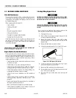
Propane Fuel System Leak Test
PROPANE IS HIGHLY FLAMMABLE AND CAN EASILY IGNITE AND CAUSE BURNS
AND SERIOUS INJURIES. NEVER USE AN OPEN FLAME OF ANY TYPE TO CHECK
FOR PROPANE FUEL SYSTEM LEAKS.
Always inspect propane fuel system for leaks after performing
service. Check for leaks at fittings of the serviced or replaced
component. Use a commercially available liquid leak detector
or an electronic leak detector. When using both methods, use
electronic leak detector first to avoid contamination by liquid
leak detector.
Summary of Contents for 450A II Series
Page 46: ...SECTION 3 CHASSIS TURNTABLE 3 6 JLG Lift 3121290 Figure 3 4 Drive Hub 4WD Front Only ...
Page 79: ...SECTION 3 CHASSIS TURNTABLE 3121290 JLG Lift 3 39 Figure 3 32 Swing Bearing Drive ...
Page 101: ...SECTION 3 CHASSIS TURNTABLE 3121290 JLG Lift 3 61 Figure 3 42 Auxiliary Pump ...
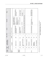
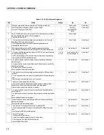
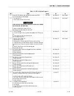
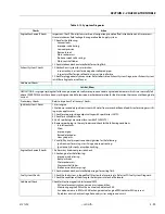
Page 113: ...SECTION 3 CHASSIS TURNTABLE 3121290 JLG Lift 3 73 Figure 3 53 EMR2 Fault Codes Sheet 1 of 5 ...
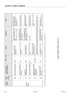
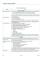
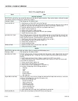
Page 114: ...SECTION 3 CHASSIS TURNTABLE 3 74 JLG Lift 3121290 Figure 3 54 EMR2 Fault Codes Sheet 2 of 5 ...
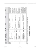
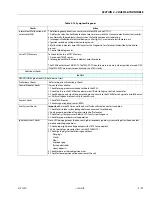
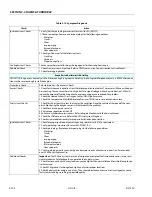
Page 115: ...SECTION 3 CHASSIS TURNTABLE 3121290 JLG Lift 3 75 Figure 3 55 EMR2 Fault Codes Sheet 3 of 5 ...
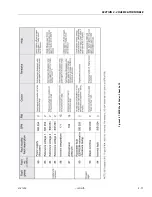
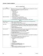
Page 116: ...SECTION 3 CHASSIS TURNTABLE 3 76 JLG Lift 3121290 Figure 3 56 EMR2 Fault Codes Sheet 4 of 5 ...
Page 117: ...SECTION 3 CHASSIS TURNTABLE 3121290 JLG Lift 3 77 Figure 3 57 EMR2 Fault Codes Sheet 5 of 5 ...
Page 159: ...SECTION 3 CHASSIS TURNTABLE 3121290 JLG Lift 3 119 ...
Page 161: ...SECTION 3 CHASSIS TURNTABLE 3121290 JLG Lift 3 121 ...
Page 163: ...SECTION 3 CHASSIS TURNTABLE 3121290 JLG Lift 3 123 ...
Page 165: ...SECTION 3 CHASSIS TURNTABLE 3121290 JLG Lift 3 125 ...
Page 173: ...SECTION 3 CHASSIS TURNTABLE 3121290 JLG Lift 3 133 Sensor Transducer Type ...
Page 177: ...SECTION 3 CHASSIS TURNTABLE 3121290 JLG Lift 3 137 Sensor Transducer Type ...
Page 179: ...SECTION 3 CHASSIS TURNTABLE 3121290 JLG Lift 3 139 ...
Page 181: ...SECTION 3 CHASSIS TURNTABLE 3121290 JLG Lift 3 141 ...
Page 183: ...SECTION 3 CHASSIS TURNTABLE 3121290 JLG Lift 3 143 ...
Page 185: ...SECTION 3 CHASSIS TURNTABLE 3121290 JLG Lift 3 145 ...
Page 187: ...SECTION 3 CHASSIS TURNTABLE 3121290 JLG Lift 3 147 ...
Page 203: ...SECTION 3 CHASSIS TURNTABLE 3121290 JLG Lift 3 163 ...
Page 207: ...SECTION 3 CHASSIS TURNTABLE 3121290 JLG Lift 3 167 ...
Page 217: ...SECTION 4 BOOM PLATFORM 3121290 JLG Lift 4 5 Figure 4 2 Boom Limit Switches ...
Page 310: ...SECTION 5 HYDRAULICS 5 70 JLG Lift 3121290 NOTES ...
Page 312: ...SECTION 6 JLG CONTROL SYSTEM 6 2 JLG Lift 3121290 Figure 6 2 Controller Block Diagram 0 ...
Page 370: ...SECTION 6 JLG CONTROL SYSTEM 6 60 JLG Lift 3121290 NOTES ...
Page 394: ...SECTION 7 BASIC ELECTRICAL INFORMATION SCHEMATICS 7 24 JLG Lift 3121290 NOTES ...
Page 395: ......


