SECTION 3 - CHASSIS & TURNTABLE
3-82
– JLG Lift –
3121290
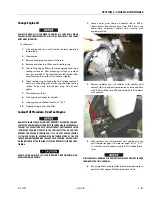
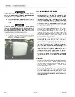
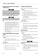
HEATED COOLANT MAY SPILL OUT DUE TO AIR “BURPING”
OUT OF SYSTEM WITH RADIATOR CAP OFF WITH ENGINE
RUNNING OR WHEN SHUTTING OFF ENGINE.
5.
Verify two coolant hoses on the EPR are warm. If they are
not warm repeat step 3 and 4, otherwise continue to
step 6.
A PROPERLY PURGED COOLING SYSTEM WILL YIELD A WARM UPPER RADIA-
TOR HOSE AND A WARM EPR HOSE. IF UPPER RADIATOR HOSE AND/OR EPR
HOSE ARE NOT WARM TO THE TOUCH AFTER ENGINE HAS RUN FOR 5-8 MIN-
UTES AFTER REACHING OPERATING TEMPERATURE, SYSTEM MAY STILL CON-
TAIN AIR. IT MAY BE NECESSARY TO REPEAT ABOVE STEPS.
6.
Fill radiator with coolant as needed and install radiator
cap. Remove cap off coolant recovery bottle and fill just
below HOT FULL line. Reinstall caps.
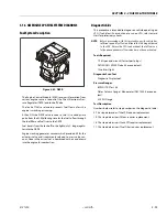
3.14 GM ENGINE DUAL FUEL SYSTEM
The fuel system installed on this engine is designed to meet
mobile engine emission standards applicable for 2010 and
later model years. The Dual Fuel system allows the vehicle to
operate on gasoline or LPG by positioning a selector switch in
the operator's platform. When the operator places the selector
switch in gasoline mode, the gasoline fuel pump is energized.
In gasoline mode the LPG fuel lock-off is isolated and will not
energize. In addition, the gasoline injector circuit is enabled
and injector pulses are provided to each injector. ECM calibra-
tion for gasoline is also enabled.
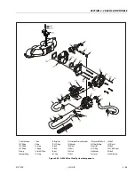
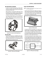
When LPG mode is selected the Low Pressure LPG lock-off is
energized and fuel from the LPG tank flows to the Electronic
Pressure Regulator (EPR). The EPR receives an electronic signal
to position the secondary lever for start or run positions. When
the engine begins to crank, the mixer air valve will rise and fuel
begins flowing to engine. During this mode the gasoline fuel
pump is isolated and is not activated.
Primary components of the gasoline dual fuel system are the
gasoline tank, electric fuel pump and filter, fuel supply line,
injector rail and injectors and the fuel pressure regulator.
Primary components of the LPG dual fuel system are the LPG
fuel tank, in-fuel filter, LPG Low Pressure lock-off, Electronic
Pressure Regulator (EPR) and the fuel mixer module. The LPG
fuel system operates at pressures which range from 14.0
inches (355.60 mm) of water column up to 312 psi (21.5 BAR).
Components shared by both systems include the Electronic
Throttle Control and ECM. The ECM contains a dual calibration;
one controls the gasoline fuel system during gasoline opera-
tion and one controls the LPG fuel system during LPG opera-
tion.
Fuel Filter
Propane fuel, like all other motor fuels, is subject to contami-
nation from outside sources. Refueling and removal of the
tank from the equipment can contaminate the fuel system. It is
necessary to filter fuel before it enters fuel system compo-
nents downstream of the tank.
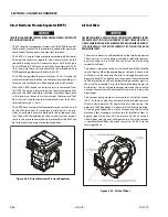
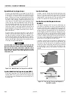
An in-line fuel filter is installed in the fuel system to remove
fuel contamination. The in-line filter is replaceable as a unit
only. Filter maintenance is critical to proper operation of the
fuel system and should be replaced as listed in Section 1. More
frequent replacement of the filter may be necessary in severe
operating conditions.
Summary of Contents for 450A II Series
Page 46: ...SECTION 3 CHASSIS TURNTABLE 3 6 JLG Lift 3121290 Figure 3 4 Drive Hub 4WD Front Only ...
Page 79: ...SECTION 3 CHASSIS TURNTABLE 3121290 JLG Lift 3 39 Figure 3 32 Swing Bearing Drive ...
Page 101: ...SECTION 3 CHASSIS TURNTABLE 3121290 JLG Lift 3 61 Figure 3 42 Auxiliary Pump ...
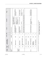
Page 113: ...SECTION 3 CHASSIS TURNTABLE 3121290 JLG Lift 3 73 Figure 3 53 EMR2 Fault Codes Sheet 1 of 5 ...
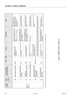
Page 114: ...SECTION 3 CHASSIS TURNTABLE 3 74 JLG Lift 3121290 Figure 3 54 EMR2 Fault Codes Sheet 2 of 5 ...
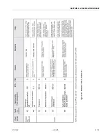
Page 115: ...SECTION 3 CHASSIS TURNTABLE 3121290 JLG Lift 3 75 Figure 3 55 EMR2 Fault Codes Sheet 3 of 5 ...
Page 116: ...SECTION 3 CHASSIS TURNTABLE 3 76 JLG Lift 3121290 Figure 3 56 EMR2 Fault Codes Sheet 4 of 5 ...
Page 117: ...SECTION 3 CHASSIS TURNTABLE 3121290 JLG Lift 3 77 Figure 3 57 EMR2 Fault Codes Sheet 5 of 5 ...
Page 159: ...SECTION 3 CHASSIS TURNTABLE 3121290 JLG Lift 3 119 ...
Page 161: ...SECTION 3 CHASSIS TURNTABLE 3121290 JLG Lift 3 121 ...
Page 163: ...SECTION 3 CHASSIS TURNTABLE 3121290 JLG Lift 3 123 ...
Page 165: ...SECTION 3 CHASSIS TURNTABLE 3121290 JLG Lift 3 125 ...
Page 173: ...SECTION 3 CHASSIS TURNTABLE 3121290 JLG Lift 3 133 Sensor Transducer Type ...
Page 177: ...SECTION 3 CHASSIS TURNTABLE 3121290 JLG Lift 3 137 Sensor Transducer Type ...
Page 179: ...SECTION 3 CHASSIS TURNTABLE 3121290 JLG Lift 3 139 ...
Page 181: ...SECTION 3 CHASSIS TURNTABLE 3121290 JLG Lift 3 141 ...
Page 183: ...SECTION 3 CHASSIS TURNTABLE 3121290 JLG Lift 3 143 ...
Page 185: ...SECTION 3 CHASSIS TURNTABLE 3121290 JLG Lift 3 145 ...
Page 187: ...SECTION 3 CHASSIS TURNTABLE 3121290 JLG Lift 3 147 ...
Page 203: ...SECTION 3 CHASSIS TURNTABLE 3121290 JLG Lift 3 163 ...
Page 207: ...SECTION 3 CHASSIS TURNTABLE 3121290 JLG Lift 3 167 ...
Page 217: ...SECTION 4 BOOM PLATFORM 3121290 JLG Lift 4 5 Figure 4 2 Boom Limit Switches ...
Page 310: ...SECTION 5 HYDRAULICS 5 70 JLG Lift 3121290 NOTES ...
Page 312: ...SECTION 6 JLG CONTROL SYSTEM 6 2 JLG Lift 3121290 Figure 6 2 Controller Block Diagram 0 ...
Page 370: ...SECTION 6 JLG CONTROL SYSTEM 6 60 JLG Lift 3121290 NOTES ...
Page 394: ...SECTION 7 BASIC ELECTRICAL INFORMATION SCHEMATICS 7 24 JLG Lift 3121290 NOTES ...
Page 395: ......

